Nerve cuff electrode locking mechanism

a technology of nerve cuff electrodes and locking mechanisms, which is applied in the field of implantable neurostimulation leads, can solve the problems of limiting the effectiveness of the nerve cuff electrode, poor sleep quality, and increased risk of cardiovascular disease and motor vehicle accidents, so as to increase the nerve diameter and prevent nerve constriction

a technology of nerve cuff electrodes and locking mechanisms, which is applied in the field of implantable neurostimulation leads, can solve the problems of limiting the effectiveness of the nerve cuff electrode, poor sleep quality, and increased risk of cardiovascular disease and motor vehicle accidents, so as to increase the nerve diameter and prevent nerve constriction

US20180318577A1Inactive Publication Date: 2018-11-08ALFRED E MANN FOUND FOR SCI RES

Image

  • Nerve cuff electrode locking mechanism
  • Nerve cuff electrode locking mechanism
  • Nerve cuff electrode locking mechanism

Examples


Embodiment Construction

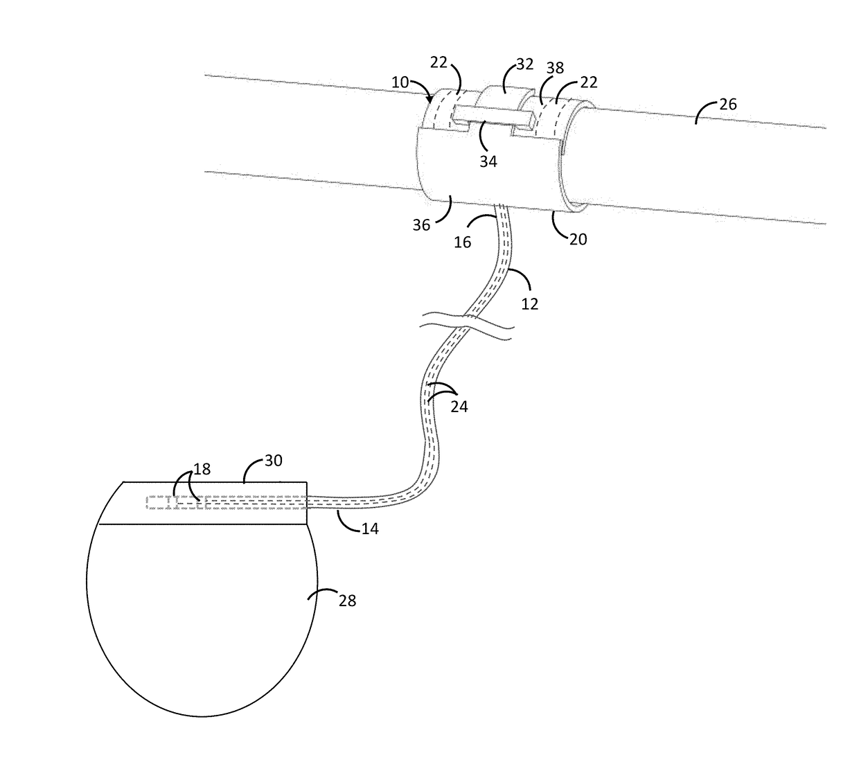
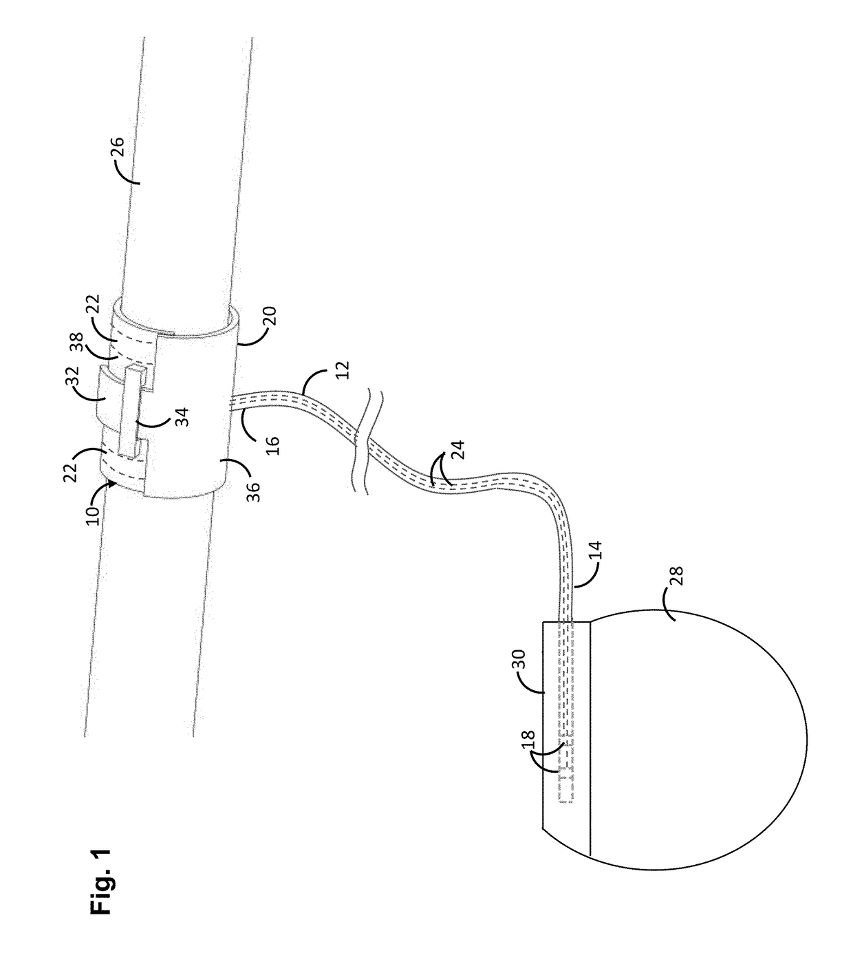
[0040]Referring to FIGS. 1-3, an electrode lead 10 constructed in accordance with one embodiment of the present invention will now be described. Although the electrode lead 10 lends itself well to be used in the treatment of OSA by stimulating the hypoglossal nerve, the electrode lead 10 may be used for any medical treatment where it is desired to stimulate a nerve.

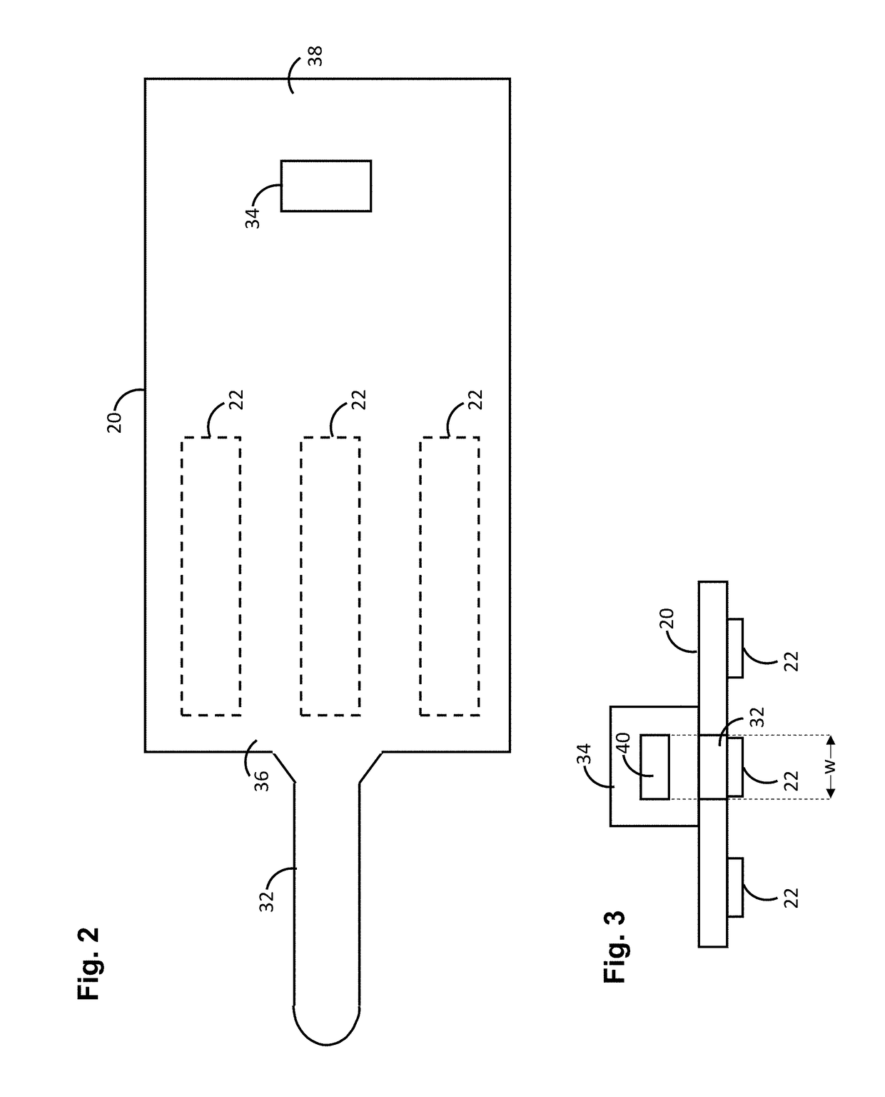
[0041]The electrode lead 10 generally comprises an elongated lead body 12 having a proximal end 14 and a distal end 16, at least one lead connector terminal 18 (two shown) affixed to the proximal end 14 of the lead body 12, a cuff body 20 affixed to the distal end 16 of the lead body 12, at least one electrode contact 22 (three shown in FIG. 2) disposed on the cuff body 20, and at least one electrical conductor 24 (two shown) extending through the lead body between the lead connector terminals 18 and the electrode contacts 22. As shown, the cuff body 20 can be circumferentially disposed around tissue, e.g., a nerve 26, su...


PUM


Abstract

A lead comprising a lead body, a lead connector terminal affixed to a proximal end of the lead body, and a cuff body affixed to a distal end of the lead body, an electrode contact affixed to the cuff body, and an electrical conductor between the connector terminal and electrode contact. The lead further comprises a strap extending from a first region of the cuff body, a buckle disposed on a second region of the cuff body, and a locking feature, e.g., protuberance, ring, or wrinkle, associated with the strap. The locking feature is configured for being pulled through the buckle to dispose the cuff body around a nerve in response to a tensile force applied to the strap. The locking feature is configured for abutting an edge of the buckle in response to a release of the tensile force to secure the cuff body around the nerve.

Description

RELATED APPLICATION DATA[0001]Pursuant to 35 U.S.C. ยง 119(e), this application claims the benefit of U.S. Provisional Patent Application 62 / 500,080, filed May 2, 2017, and U.S. Provisional Patent Application 62 / 500,091, filed May 2, 2017, which are expressly incorporated herein by reference. This application is also related to U.S. patent application Ser. No. ______ (Attorney Docket No. AMF-006US (A697-USA)), filed on the same date, which is expressly incorporated herein by reference.FIELD OF THE INVENTION[0002]The present invention generally relates to implantable neurostimulation leads, and specifically relates to implantable nerve cuff electrodes that can be used to stimulate nerves to treat ailments, such as obstructive sleep apnea (OSA).BACKGROUND OF THE INVENTION[0003]Obstructive sleep apnea (OSA) is a common disorder in which the upper airway of a patient can become obstructed (apnea) or partially obstructed (hypopnea) during sleep. It is highly prevalent, affecting 5%-10% of...

Claims


Application Information

Patent Timeline
08 Nov 2018
Publication
US20180318577A1
IPC
A61N1/05; A61B5/00
CPC
A61N1/0556; A61N1/0558; A61B5/4818; A61B5/686; A61B5/6877; A61B2562/0209; A61B5/24; A61B5/296
Inventors
NG, BOON KHAI; SCHMIDT, SIEGMAR