LIDAR Device Based on Scanning Mirrors Array and Multi-Frequency Laser Modulation

a laser modulation and mirror array technology, applied in the field of laser modulation devices based on scanning mirror arrays and multi-frequency laser modulation, can solve the problems of limiting the acceptable laser power of state-of-the-art lidars such as energy consumption and operating temperature requirements, and achieve the effect of reducing background nois

Active Publication Date: 2018-11-15
MASSACHUSETTS INST OF TECH
View PDF10 Cites 31 Cited by
  • Summary
  • Abstract
  • Description
  • Claims
  • Application Information

AI Technical Summary

Benefits of technology

[0006]In one embodiment the LiDAR device with a stationary housing includes a single light source to generate continuous waves or discontinuous pulses of light. It also includes a single projection lens that captures and collimates the projection light. A collimation stage aims to adjust the divergence of emitted light in a suitable fashion in order to maximize the detection range. The light source generates light at a single or a plurality of wavelengths suitable for light detection and ranging in various environmental conditions such as night, day, rain or fog. The light wavelengths can be switched to suitable values as the environmental conditions vary. At least part of the light pathway in the LiDAR setup is shared between the projection and detection portions of the LiDAR. The projection light is guided to the shared pathway via a stationary mirror placed at a suitable angle with respect to the direction of the light emitted by the light source. This stationary mirror enables placement of the light source outside the shared detection / projection pathway. The projection light is then directed to the objects in the environment via a scanning mirrors array containing a multitude of moving mirror components. The reflected light is captured in the same direction by the same multitude of scanning mirrors and directed towards a lens hereafter referred to as the detection lens that focuses the incoming reflected beams of light onto one or a multitude of detectors.
[0011]This invention further includes techniques for unambiguous detection and processing of light reflections for high-rate and dense-point-cloud formation and for large-detection-ranges. In one example the power of emitted light is modulated over a range of frequencies. The range of applied frequencies are dependent on the required maximum pulsing rate and the expected maximum detection range. The emitted light intensity can form a continuous wave featuring a modulated frequency or a discontinuous series of light pulses resembling a wavelet each featuring a specific modulation frequency. As such, the frequency signature of the reflecting light determines the timing of the corresponding light emission and the TOP associated with every detected reflection can be estimated without any ambiguity. Another benefit of modulating the light intensity at known frequencies is the significant reduction of the background noises in day light when sunlight interferences can be substantial or harsh weather conditions where intensity of reflected light is very low (i.e. low detection SNR).
[0012]In another example the wavelength of the emitted light can be modulated over time. In this form bandpass optical filters can be used to guide the emitted lights of various wavelengths to specific detectors and hence to remove any ambiguity in detection and ranging.

Problems solved by technology

However, the point cloud density in state of the art LiDARs such as in [(1, 2] is often very low due to a limited number of laser sources and, similarly, a limited number of detectors.
Given the space and cost constraints there is often a limited number of laser diodes and detectors that can be accommodated in a LiDAR system.
Eye safety, energy consumption and also operating temperature requirements limit acceptable laser power.
Low laser power, limited detection dynamic range and short duration of laser pulses combined with often very weak diffusive reflection off the majority of surfaces make detection of reflected light very challenging.
This challenge is even greater in outdoor applications where background lighting can undermine detectability of reflected light.
However, large lenses feature large focal distance and hence have a very limited field of view.
Such a pulsing rate is not sufficient for building dense point clouds at a reasonable frame / sweep rate relevant to applications such as autonomous driving or high speed robotics, etc.
The requirement for unambiguous detection of reflected light further limits the feasible pulsing rate.
Although application of multiple laser sources and multiple sensors is feasible, it brings about severe cost and resolution constraints and limits the capabilities of LiDARs.

Method used


Image

  • LIDAR Device Based on Scanning Mirrors Array and Multi-Frequency Laser Modulation
  • LIDAR Device Based on Scanning Mirrors Array and Multi-Frequency Laser Modulation
  • LIDAR Device Based on Scanning Mirrors Array and Multi-Frequency Laser Modulation

Examples


Embodiment Construction

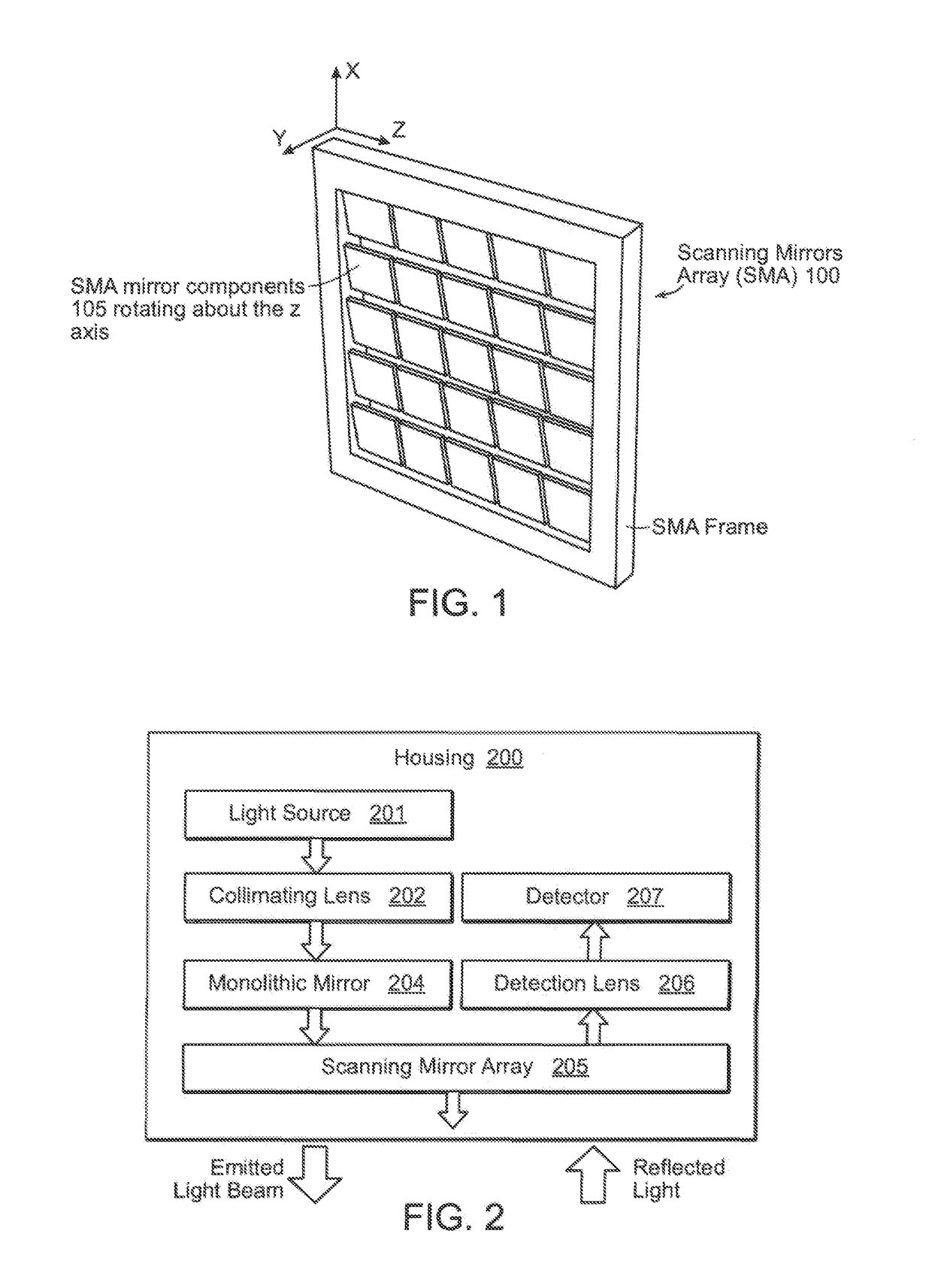
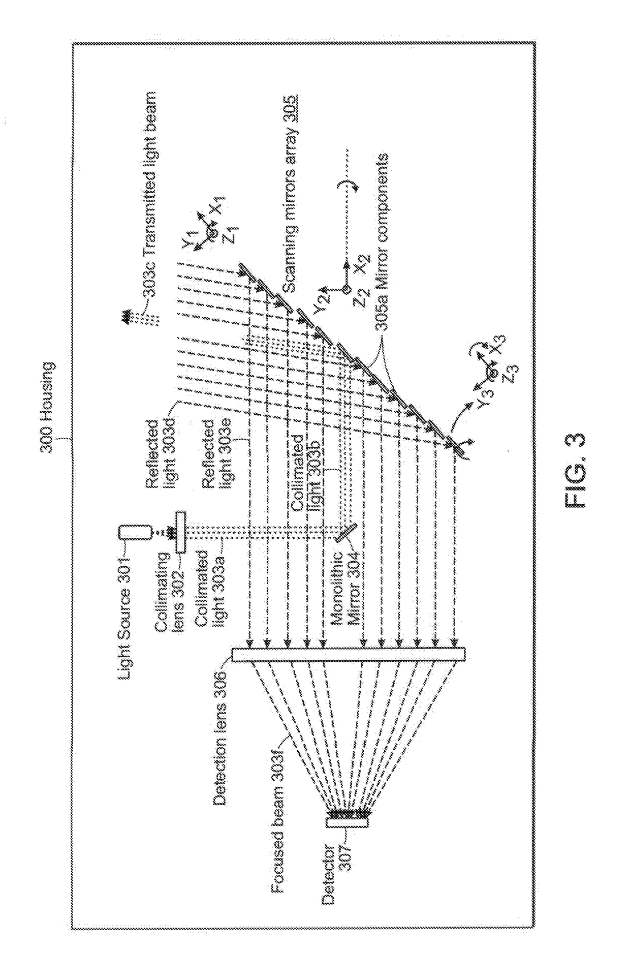
[0034]The LiDAR device according to this invention may include a single or a multitude of light sources, and a single or a multitude of detectors. By projecting continuous waves or discontinuous light pulses onto various objects and measuring certain features of the reflected light e.g. time of flight (TOF) or phase lag with respect to the projected light one can estimate the distance of various objects in the environment and form a point cloud of the surroundings. Such information can be very useful in various applications such as autonomous driving and robotics. State of the art designs of LiDARs are often very limited in terms of data throughput and resolution. Furthermore, due to a need for multiple detectors and light sources the design and calibration can be complex and the associated manufacturing cost can be very high. Furthermore, such designs often leave very limited room for flexibility and on the fly tuning / changing of various characteristics of the instrument such as wa...


PUM


Abstract

A LiDAR device that transmits a single or multiple continuous or intermittent laser beams to the environment and detects the reflected light on one or more detectors. The LiDAR device may include a scanning mirrors array composed of a single or multiple moving mirrors capable of changing the direction of the transmitted light. The scanning mirrors array may also include sensors and actuators which can be used to precisely control or measure the position of the mirrors. The LiDAR device may also include a lens that focuses the light captured by the mirror(s) onto a single or a multitude of detectors. The device may include laser sources and detectors operating in various wavelengths. The LiDAR device may also include laser power modulation mechanisms at a single or multitude of frequencies to improve signal detection performance and remove any ambiguity in range calculation.

Description

BACKGROUND OF THE INVENTION[0001]Accurate knowledge of the environment such as shape, color, distance and arrangement of various objects in the surroundings can be useful in robotic applications, aerial or underwater vehicles or autonomous driving. Of the multiple sensing options in such applications, light detection and ranging devices (LiDARs) have certain advantages, e.g., resolution, range and precision. A LiDAR can estimate the distance to or geometric features of surroundings on a point by point basis to form a point cloud of reachable or visible objects. To measure points in the cloud, individual pulses of light can be projected onto various objects and the associated time of flight (time between the transmission of light and the detection of the reflection) can be estimated. To cover the area of interest in the environment and form a point cloud, pulses of light can be issued repeatedly in various directions. The orientation of the projected laser and the measured time of fl...

Claims


Application Information

Patent Timeline
Patent Type & Authority Applications(United States)
IPC IPC(8): G01S7/481G01S17/08G01S17/26G01S17/931
CPCG01S17/08G01S7/4817G01S17/42G01S7/4815G01S7/4816G01S2013/93277G01S17/26G01S17/931
Inventor BOZCHALOOI, IMAN SOLTANIYOUCEF-TOUMI, KAMAL
Owner MASSACHUSETTS INST OF TECH
Why Eureka
Try Eureka