Method of manufacturing metal-clad laminate and uses of the same

Active Publication Date: 2018-11-29
TAIWAN POWDER TECH CO LTD
View PDF1 Cites 8 Cited by
  • Summary
  • Abstract
  • Description
  • Claims
  • Application Information

AI Technical Summary

Benefits of technology

[0007]In view of the aforementioned technical problems, the present invention provides a manufacturing method of a fluoropolymer metal-clad laminate. The manufacturing method of the present invention does not use any additional fluoropolymer film as an adhesive layer or involve any atta

Problems solved by technology

Conventional electronic material made from an epoxy resin are failing to keep up with the trends of high-frequency and high-speed signal transmission, miniaturization of electronic elements, and high-density wiring of circuit boards.
However, electronic materials including a dielectric layer made of the fluoropolymer, e.g., a metal-clad laminate, have poor metal peeling strength because the bonding strength between the fluoropolymer and the metal foil of the laminate is weak.
Furthermore, when a low profile metal foil is used in such a metal-clad laminate out of consideration for electrical properties (e.g., a lower dielectric loss), the bonding strength between the metal foil and the fluoropolymer is even weaker because the metal foil has lower surface roughness.
However, the epoxy resin-based adhesive has poor dielectric properties and thus deteriorates the electrical properties of the resultant electronic material.
However, the aforementioned method has at

Method used


Image

  • Method of manufacturing metal-clad laminate and uses of the same

Examples


Example

Example 1

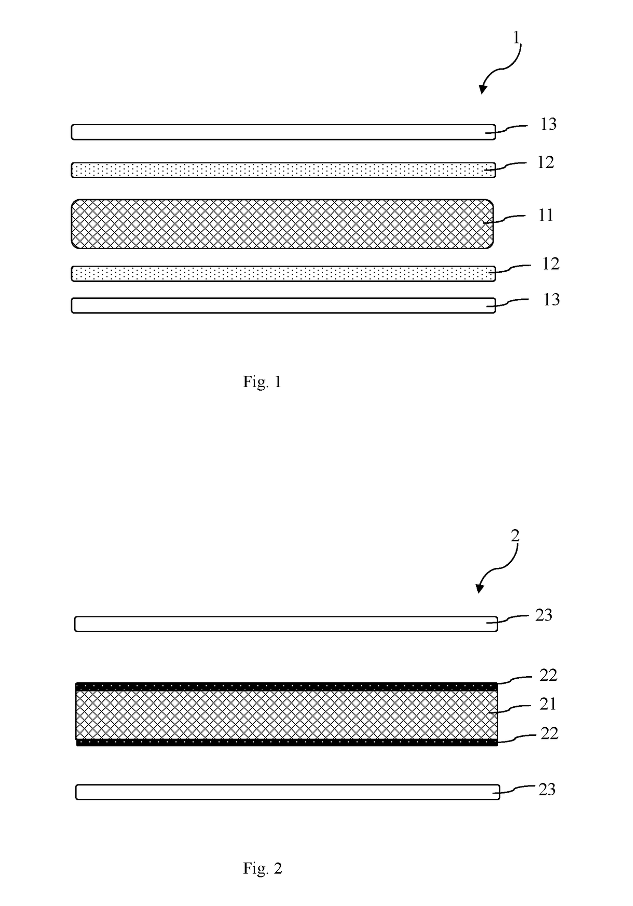
[0043]As shown in Table 1, an E-glass fiber fabric (1080 type) was impregnated with a PTFE dispersing emulsion (trade name: DISP 30, available from DuPont, PTFE solid content is 60 wt %), and the impregnated E-glass fiber fabric was then baked at a low temperature of 250° C. to dry the PTFE dispersing emulsion. The above impregnating and drying steps were repeated such that the E-glass fiber fabric was impregnated with the PTFE dispersing emulsion twice to obtain a PTFE sheet. Next, the PTFE sheet was impregnated with a PFA dispersing emulsion (trade name: PFA355D, available from DuPont, PFA solid content is 60 wt %) and then baked at 200° C. to dry the PFA dispersing emulsion. The above impregnating and drying steps were repeated such that the PTFE sheet was impregnated twice and a PFA-coated PTFE sheet was obtained. Afterwards, two sheets of HTE type copper foil (0.5 oz., trade name: PLS, available from CCP) were respectively superimposed on both of the two outer surfaces...

Example

Example 2

[0044]The preparation procedures of Example 1 were repeated to prepare a copper-clad laminate 2, except that the impregnated E-glass fiber fabric was baked at a high temperature of 370° C. to dry the PTFE dispersing emulsion, as shown in Table 1.

Example

Example 3

[0045]The preparation procedures of Example 1 were repeated to prepare a copper-clad laminate 3, except that the PTFE sheet was impregnated with the PFA dispersing emulsion once, as shown in Table 1.


PUM

PropertyMeasurementUnit
Temperatureaaaaaaaaaa

Abstract

A method of manufacturing a metal-clad laminate and uses of the same are provided. The method comprises the following steps:
    • (a) impregnating a reinforcement material with a first fluoropolymer solution, and drying the impregnated reinforcement material under a first temperature to obtain a first prepreg;
    • (b) impregnating the first prepreg with a second fluoropolymer solution, and drying the impregnated first prepreg under a second temperature to obtain a second prepreg; and
    • (c) laminating the second prepreg and a metal-clad to obtain a metal-clad laminate,
    • wherein the first fluoropolymer solution has a first fluoropolymer, the second fluoropolymer solution has a second fluoropolymer, and the first fluoropolymer and the second fluoropolymer are different.

Description

CLAIM FOR PRIORITY[0001]This application claims the benefit of Taiwan Patent Application No. 106117171 filed on May 24, 2017, the subject matters of which are incorporated herein in their entirety by reference.BACKGROUND OF THE INVENTIONField of the Invention[0002]The present invention provides a manufacturing method of a metal-clad laminate and uses of the same. Especially, a manufacturing method of a fluoropolymer metal-clad laminate as well as a fluoropolymer metal-clad laminate and a printed circuit board prepared by the method are provided. The fluoropolymer metal-clad laminate prepared by the method of the present invention can be used as a circuit board that is suitable for high-frequency technical fields, such as radio frequency (RF) technical field, microwave technical field, antenna technical field and radar technical field.Descriptions of the Related Art[0003]There are strict requirements on the physicochemical properties of electronic materials because electronic product...

Claims


Application Information

Patent Timeline
IPC IPC(8): B32B15/08C08J5/24C08J5/04C08J5/12B32B37/14H05K1/03H05K3/38
CPCB32B15/08C08J5/24C08J5/043C08J5/124B32B37/14H05K1/0353H05K3/381C08J2327/18C08J2429/10C08J2427/18B32B2457/08H05K2201/015B32B15/04B32B15/085B32B15/09B32B15/14B32B37/10B32B38/08H05K3/4611B32B2260/021B32B2260/046B32B2262/101C08J5/244B32B37/06B32B37/18B32B2037/0092B32B2305/076B32B2309/68B32B2311/00H05K1/0366H05K3/022B32B2264/108B32B15/20B32B2264/107B32B2264/12B32B2307/204B32B5/022B32B2262/02B32B2264/10B32B2255/02B32B2255/26B32B5/024B32B2250/40B32B2264/0257B32B2262/0269B32B2264/101B32B2250/03B32B2262/0253B32B2264/102B32B2307/538B32B15/18B32B2307/748B32B2264/104B32B2307/308B32B2307/202B32B2262/0276
Inventor CHEN, WEN-RENLIU, SHUR-FEN
Owner TAIWAN POWDER TECH CO LTD
Why Eureka
Try Eureka