
Low Wideband Noise Multi-Stage Switch-Mode Power Amplifier

Active Publication Date: 2018-11-29
ERIDAN COMM
View PDF2 Cites 4 Cited by
  • Summary
  • Abstract
  • Description
  • Claims
  • Application Information

AI Technical Summary

Benefits of technology

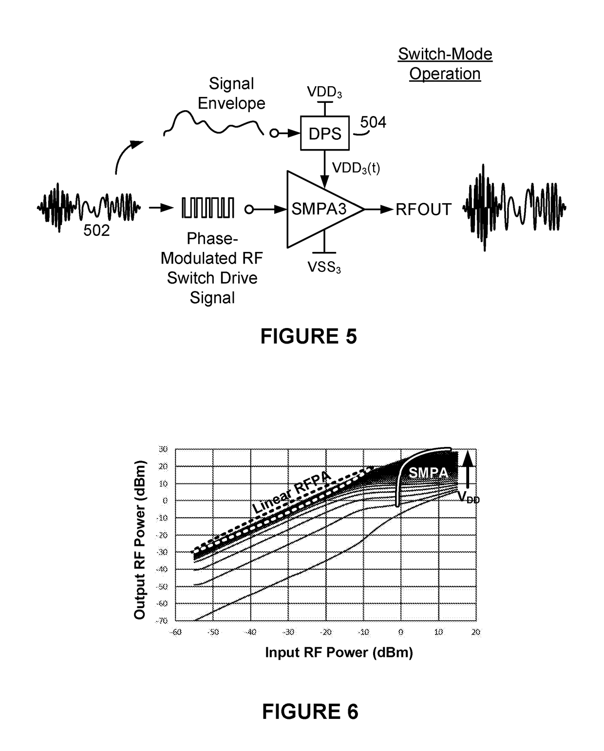
The patent describes a multi-stage RF power amplifier that uses a plurality of switch-mode power amplifiers to minimize distortion and noise in RF output. The amplifier operates by dynamically minimizing the magnitude of the RF switch drive signal based on the characteristics of the output stage's power transistor and its changing load line. This reduces amplifier distortion and achieves high energy efficiency and low WBN in the output RF spectrum. The technical effect of this patent is to improve RF power amplification while reducing distortion and noise.

Problems solved by technology

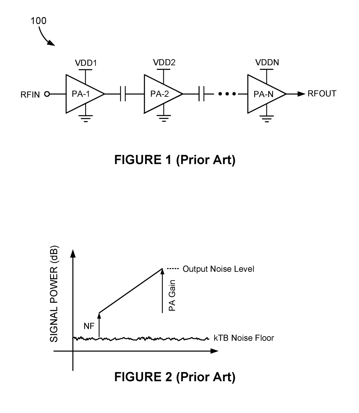
Often an RFPA will not have sufficient power gain to translate the low-power RF input signal to the desired or needed RF power.
Unfortunately, these so-called “linear” RFPAs are very energy inefficient.
Energy efficiency of any given stage is especially low during times the magnitude of its input RF signal is low, and particularly problematic in circumstances where the input RF signal RFIN is amplitude modulated.
. . ,PA-N must be “backed off” Unfortunately, while backing off the output RF powers does help to maintain linearity, it further lowers the energy efficiency of the multi-stage RFPA 100.
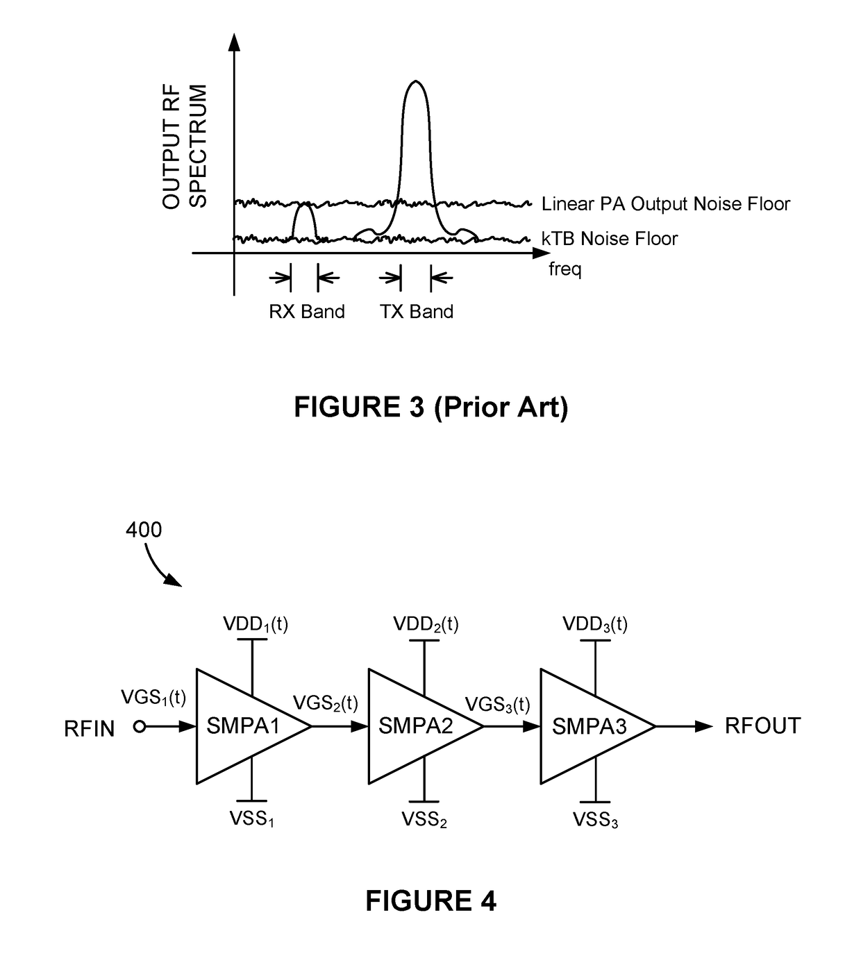
Another problem with the multi-stage RFPA 100 is that it produces a significant amount of wideband noise (WBN).
. . ,PA-N are not ideal devices and are themselves sources of noise, their mere presence increases WBN above the kTB thermal noise floor.
In some circumstances the WBN can be so high that it is impossible to satisfy the spectral mask requirements specified by an applicable communications standard.

Method used


Image

  • Low Wideband Noise Multi-Stage Switch-Mode Power Amplifier
  • Low Wideband Noise Multi-Stage Switch-Mode Power Amplifier
  • Low Wideband Noise Multi-Stage Switch-Mode Power Amplifier

Examples


Embodiment Construction

[0029]Referring to FIG. 4, there is shown a multi-stage radio frequency power amplifier (RFPA) 400, according to one embodiment of the present invention. The multi-stage RFPA 400 comprises a plurality of switch-mode power amplifiers (SMPAs), three in this exemplary embodiment labeled SMPA1, SMPA2 and SMPA3. As their names suggest, each of the SMPAs: SMPA1, SMPA2 and SMPA3 is configured to operate as a switch, unlike the linear PAs: PA-1, PA-2, . . . ,PA-N of the multi-stage RFPA 100 described above in reference to FIG. 1 which operate as controlled current sources (i.e., “linear” PAs). Further, each of the SMPAs: SMPA1, SMPA2 and SMPA3 is configured to operate in the polar domain, in response to amplitude-modulated power supply voltages VDD1(t), VDD2(t), and VDD3(t) applied to their respective power supply ports and square waveform angle-modulated switch drive signals VGS1(t), VGS2(t), and VGS3(t) applied to their RF input ports. In the description that follows, it is assumed that b...


PUM


Abstract

A multi-stage radio frequency power amplifier (RFPA) includes an output stage SMPA and a driver stage SMPA. As the multi-stage RFPA operates, the magnitude of an RF switch drive signal generated by the driver stage SMPA is dynamically minimized based on I-V characteristic curves of the output stage SMPA's power transistor and the output stage SMPA's dynamically changing load line. By constraining the magnitude of the RF switch drive signal as the multi-stage RFPA operates, VGS feedthrough of the RF switch drive signal is minimized, to the extent possible. Amplitude distortion and phase distortion in the RF output that might occur due to unconstrained VGS feedthrough, particularly at low output RF power levels, are therefore avoided. Operating all stages of the multi-stage RFPA in switch mode also results in high energy efficiency and an output RF spectrum with very low wideband noise (WBN).

Description

CROSS-REFERENCE TO RELATED APPLICATIONS[0001]This application claims the benefit of U.S. Provisional Patent Application No. 62 / 509,859, filed on May 23, 2017.BACKGROUND OF THE INVENTION[0002]Radio frequency power amplifiers (RFPAs) are used to translate RF signals, such as a modulated RF carrier in an RF transmitter, to higher RF powers. Often an RFPA will not have sufficient power gain to translate the low-power RF input signal to the desired or needed RF power. To address this limitation, RFPAs are often constructed from two or more RFPAs (or “stages”), as illustrated in FIG. 1. The total power gain G of the multi-stage RFPA 100 is determined by the product of the power gains of all of its N individual stages, where N denotes the number of stages. In other words, G=G1×G2× . . . GN, where G1, G2 and GN are the power gains of the individual stages PA-1, PA-2, and PA-N, respectively. When expressed in decibels (dB), the total power gain G(dB) is the sum of the individual power gains,...

Claims


Application Information

Patent Timeline
IPC IPC(8): H03F3/193H03F3/217H03F3/45H02M3/335H02M1/32H02M1/36
CPCH02M1/36H03F3/193H03F3/2171H03F3/45H02M3/33507H02M1/32H02M3/156H03F1/0222H03F2200/102H03F2200/405H03F2200/451
Inventor MCCUNE, JR., EARL WDIDUCK, QUENTIN
Owner ERIDAN COMM
Learn More