Steam reforming catalyst for hydrocarbons

a catalyst and steam technology, applied in the field of steam reforming catalysts, can solve the problems of increasing hydrogen production costs, and achieve the effect of preventing the catalytic activity reduction and high conversion from hydrocarbons

Inactive Publication Date: 2018-12-06
SANTOKU CORP
View PDF2 Cites 3 Cited by
  • Summary
  • Abstract
  • Description
  • Claims
  • Application Information

AI Technical Summary

Benefits of technology

[0011]The steam reforming catalyst of the present invention contains the catalyst carrier containing particular amounts of the particular elements, and further contains particular amounts of the Ni and Ti supported on the catalyst carrier. Consequently, the steam reforming catalyst can prevent the catalytic activity reduction by the sulfur poisoning, and can maintain a high conversion from the hydrocarbon to hydrogen, without using expensive noble metals.

Problems solved by technology

Therefore, an advanced desulfurization apparatus is required in the desulfurization step to increase the hydrogen production cost.

Method used


Image

  • Steam reforming catalyst for hydrocarbons

Examples


example 1

[0065]37.5 g of a zirconium oxynitrate solution (7.5 g in terms of ZrO2), 10.35 g of nitric acid (7.0 g in terms of HNO3), and 900 mL of pure water were added to a 2-L separable beaker, and the resultant mixture was stirred to prepare an aqueous zirconium solution.

[0066]The aqueous zirconium solution was heated to 98° C. by a mantle heater, and stirred under heating reflux for 8 hours [step (a)].

[0067]Then, 131 mL of a cerium (IV) nitrate solution (an aqueous cerium solution, 26.2 g in terms of CeO2) was added to the aqueous zirconium solution to prepare a mixed aqueous solution. The mixed aqueous solution was heated to 98° C. again by a mantle heater, and stirred under heating reflux for 20 hours [step (b-1)].

[0068]The solution obtained from the step (b-1) was put into a 3,000-mL beaker, and 10.4 mL of a praseodymium nitrate solution (an aqueous additional element solution, 5.2 g in terms of Pr2O3) and 1,000 mL of pure water were added to the beaker. The resultant mixture was stirr...

example 2

[0079]A steam reforming catalyst of Example 2 was produced in the same manner as Example 1 except that the amount of the cerium (IV) nitrate solution used in the step (b-1) was 52.5 mL (10.5 g in terms of CeO2), the amount of the praseodymium nitrate solution used in the step (b-2) was 2.1 mL (1.05 g in terms of Pr2O3), the amount of the alumina sol BIRAL AL-7 available from Taki Chemical Co., Ltd. was 9.53 g, and the amount of the methylcellulose was 0.57 g. The steam reforming catalyst of Example 2 was subjected to the measurements in the same manner as Example 1. The results are shown in Tables 1 and 2.

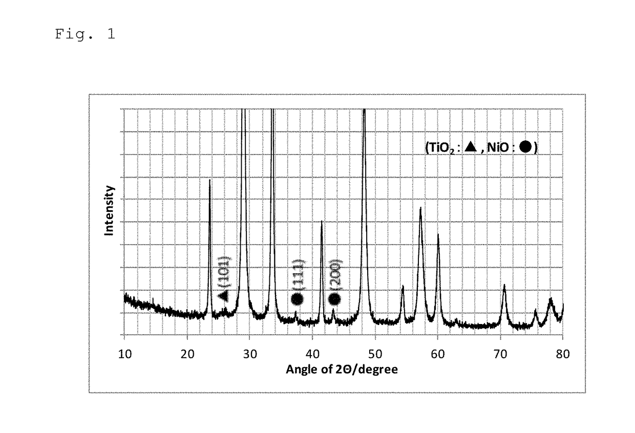
[0080]The Ce content per 1 mol of the Zr was 1.0 mol. The Ni content was 83.6% by mole, and the Ti content was 16.4% by mole.

example 3

[0081]A steam reforming catalyst of Example 3 was produced in the same manner as Example 1 except that the amount of the cerium (IV) nitrate solution used in the step (b-1) was 157.5 mL (31.5 g in terms of CeO2), the amount of the praseodymium nitrate solution used in the step (b-2) was 2.1 mL (1.05 g in terms of Pr2O3), the amount of the alumina sol BIRAL AL-7 available from Taki Chemical Co., Ltd. was 20.0 g, and the amount of the methylcellulose was 1.2 g. The steam reforming catalyst of Example 3 was subjected to the measurements in the same manner as Example 1. The results are shown in Tables 1 and 2.

[0082]The Ce content per 1 mol of the Zr was 3.0 mol. The Ni content was 83.6% by mole, and the Ti content was 16.4% by mole.


PUM

PropertyMeasurementUnit
temperatureaaaaaaaaaa

Abstract

There is provided a steam reforming catalyst comprising a carrier and a catalyst supported thereon. The carrier contains a composite oxide containing Ce and Zr. The content of the Ce is not less than 1.0 mol and not more than 3.0 mol per 1 mol of the Zr. The catalyst contains Ni and Ti. The content of the Ni is not less than 70% and not more than 97% by mole, and the content of the Ti is not less than 3% and not more than 30% by mole, based on 100% by mole of the total of the Ni and Ti.

Description

FIELD OF ART[0001]The present invention relates to a steam reforming catalyst containing Ni and Ti for reforming a hydrocarbon.BACKGROUND ART[0002]In recent years, various researches have been actively made on fuel cell vehicles, household fuel cells, hydrogen power generation systems, and the like, for the purpose of realizing hydrogen society utilizing hydrogen energy. Also various hydrogen production technologies have been researched, and currently steam reforming processes, which contains reforming a hydrocarbon via a reaction with a water vapor to produce hydrogen, are mainly studied. A catalyst is needed to efficiently carry out the steam reforming reaction, and examples of such catalysts include noble metal catalysts and Ni-based catalysts.[0003]It is well known that the steam reforming catalyst for reforming the hydrocarbon is inactivated when poisoned by a sulfur content in the hydrocarbon material. In general, in the hydrogen production process, a desulfurization step for ...

Claims


Application Information

Patent Timeline
Patent Type & Authority Applications(United States)
IPC IPC(8): B01J23/83B01J23/46B01J23/755B01J23/89B01J37/04B01J37/08C01B3/40
CPCB01J23/755B01J35/1014B01J37/04B01J23/464C01B3/40B01J23/894B01J23/83B01J37/08B01J23/002B01J35/002B01J35/008B01J35/023B01J35/08B01J37/0018B01J37/0201B01J37/03B01J2523/00Y02P20/52B01J2523/31B01J2523/3712B01J2523/3718B01J2523/47B01J2523/48B01J2523/847
Inventor MUROTA, TADATOSHITAHARA, TOMONORI
Owner SANTOKU CORP
Why Eureka
Try Eureka