
Sonication-assisted fuel deoxygenation

a technology of fuel deoxygenation and sonication, which is applied in the direction of liquid degasification, separation processes, lighting and heating apparatus, etc., can solve the problems of limited life, degradation of performance, and challenges of such systems

Active Publication Date: 2018-12-06
HAMILTON SUNDSTRAND CORP
View PDF19 Cites 1 Cited by
  • Summary
  • Abstract
  • Description
  • Claims
  • Application Information

AI Technical Summary

Benefits of technology

The patent describes a system that removes oxygen from fuel using ultrasound waves. This system includes a deoxygenator, an ultrasound transducer, and a control. The system can be used in gas turbine engines to improve fuel quality. The patent also includes a method for using the system. The technical effect of the system is to improve fuel quality in gas turbine engines, which can lead to better performance and efficiency.

Problems solved by technology

As more heat is transferred to the fuel, temperatures rise, and dissolved oxygen combined with this high temperature result in fuel varnish / coke coating internal surfaces of fuel line components and nozzles, causing degraded performance and limited life.
However, there are challenges with such systems.

Method used


Image

  • Sonication-assisted fuel deoxygenation

Examples


Embodiment Construction

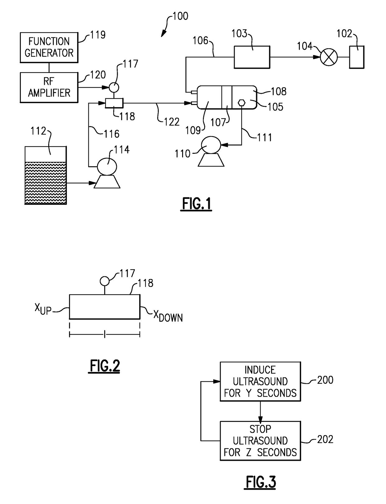
[0013]A fuel supply system 100 is illustrated in FIG. 1 for a gas turbine engine 102. As known, a high pressure fuel pump 104 delivers fuel to a combustor on the engine 102. A supply line 106 supplies the fuel downstream of a deoxygenator 108. This deoxygenator is shown schematically. A second optional oxygen removal system 103 is included. The details of this disclosure may be utilized separately from any such second deoxygenator or may be utilized to supplement less efficient deoxygenators 103.

[0014]Deoxygenator 108 includes a membrane 107. As known, fuel enters a chamber 109 in the deoxygenator 108 and oxygen passes across the membrane into a chamber 105 from which it can be removed through a vent line 111 by a vacuum source 110. The operation of such systems is as known. However, as mentioned above, it is challenging to bring the majority of the oxygen in the fuel into contact with the membrane.

[0015]While a membrane type deoxygenator is specifically disclosed, it should be unde...


PUM

PropertyMeasurementUnit
Timeaaaaaaaaaa
Timeaaaaaaaaaa
Timeaaaaaaaaaa

Abstract

A fuel deoxygenation system has a deoxygenator, an ultrasound transducer, and a control. The ultrasonic transducer is operable to direct ultrasonic waves into a flow passage for a fuel connected to the deoxygenator. A gas turbine engine and a method are also disclosed.

Description

BACKGROUND OF THE INVENTION[0001]This application relates to a system which utilizes ultrasonic waves to create gas bubbles in a fuel flow.[0002]Gas turbine engines are known and typically include a number of systems. As one example, a fuel supply system supplies fuel to a combustor. Typically, a fuel pump delivers the fuel from a fuel tank.[0003]Inevitably, oxygen is mixed into the fuel. Transferring heat to fuel helps provide thermal control for valves, pumps, electronics, and gearboxes, among other ancillary hardware. As more heat is transferred to the fuel, temperatures rise, and dissolved oxygen combined with this high temperature result in fuel varnish / coke coating internal surfaces of fuel line components and nozzles, causing degraded performance and limited life. As such, it is known to attempt to remove the dissolved oxygen from the fuel prior to its use as a heat sink.[0004]A number of systems have been developed. In one such system, a membrane is placed within a deoxygena...

Claims


Application Information

Patent Timeline
IPC IPC(8): F02M27/08F23K5/08B01J19/10B01D19/00
CPCF02M27/08F23K5/08B01J19/10F23K2900/05082B01D19/0031F23N2041/20B01D19/0094B01D19/0078F02C7/22F23N2241/20
Inventor STAROSELSKY, ALEXANDERCORDATOS, HARALAMBOS
Owner HAMILTON SUNDSTRAND CORP
Learn More