Antibacterial nonwoven member, antibacterial nonwoven fabric, and antibacterial buffer material
a technology of antibacterial nonwoven fabric and antibacterial material, which is applied in the direction of weaving, protective garments, special outerwear garments, etc., can solve the problems of allergic reaction, failure to keep excellent antibacterial action for a long time, and the like, and achieves the effect of reducing the distance between the first and second yarns, high antibacterial action, and large electric field generated by the cloth
- Summary
- Abstract
- Description
- Claims
- Application Information
AI Technical Summary
Benefits of technology
Problems solved by technology
Method used
Image
Examples
first embodiment
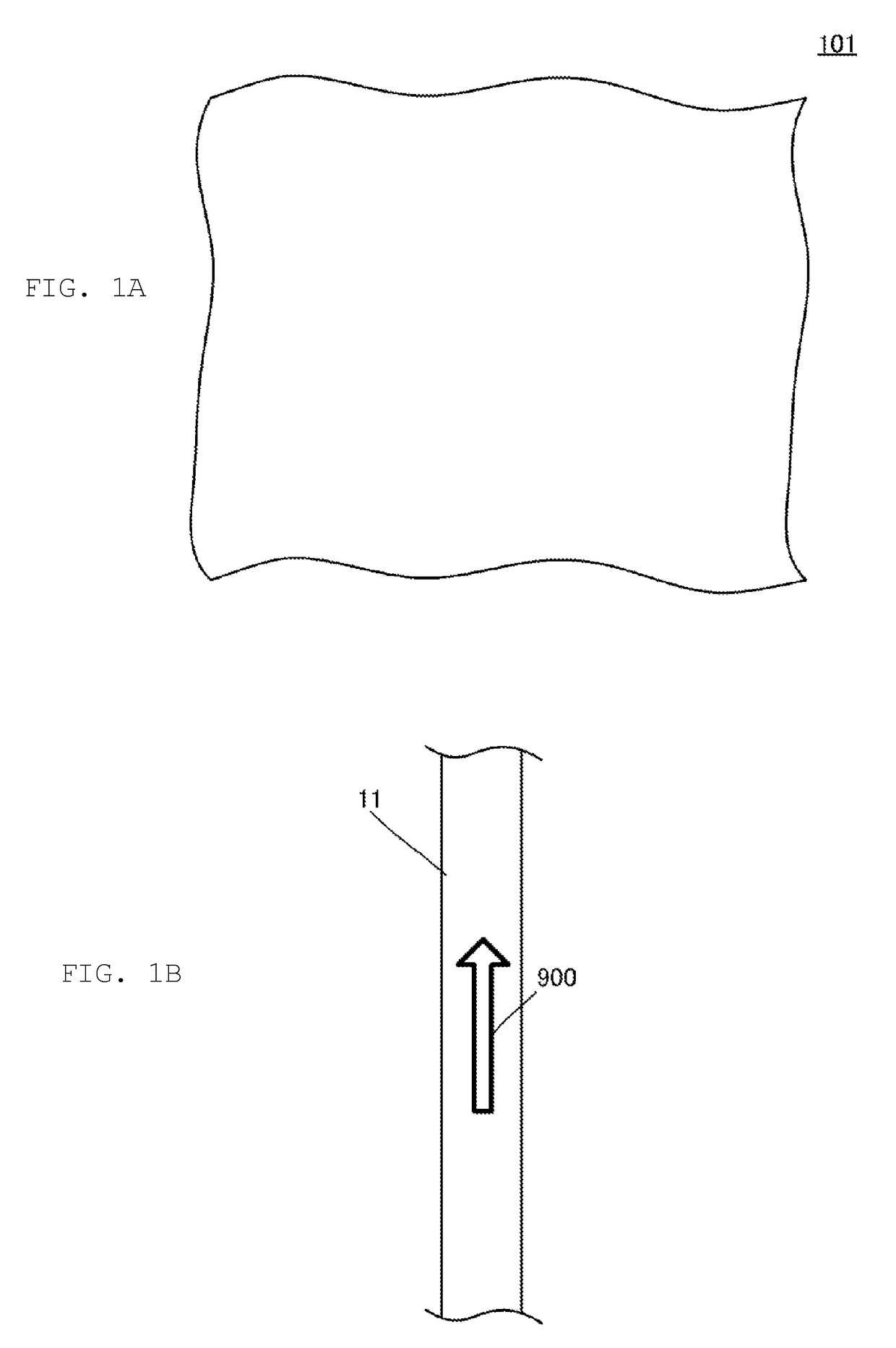
[0055]FIG. 1A is a schematic plan view of a nonwoven member 101 according to a first embodiment, and FIG. 1B is a plan view of a piezoelectric fiber 11 forming the nonwoven member 101. The nonwoven member 101 is a nonwoven fabric. The nonwoven fabric is an example of the “nonwoven member” in the present invention.
[0056]The nonwoven member 101 includes a plurality of piezoelectric fibers 11. The nonwoven member 101 of the present embodiment is formed into a cloth (sheet) by intertwining the plurality of piezoelectric fibers 11. The piezoelectric fiber 11 is an example of the “piezoelectric body” in the present invention.
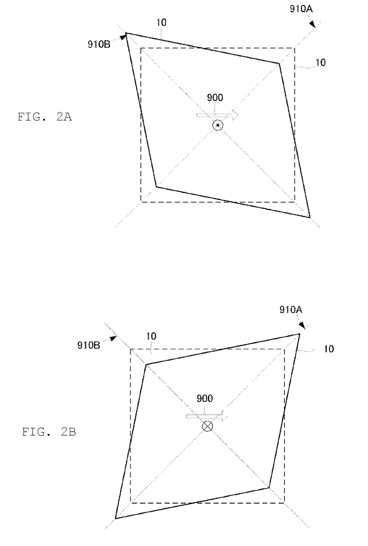
[0057]The piezoelectric fiber 11 is made of, for example, a piezoelectric polymer. Some of the piezoelectric fibers 11 are pyroelectric and some are not. For example, polyvinylidene fluoride (PVDF) is pyroelectric and generates an electric charge due to temperature change. Polylactic acid (PLA) is a piezoelectric body not having pyroelectricity. Polylactic acid is uni...
second embodiment
[0068]The second embodiment shows an example in which the nonwoven member of the present invention is a buffer material.
[0069]FIG. 4A is an outline view of a nonwoven member 102 according to a second embodiment and FIG. 4B is an enlarged view of a DP1 portion shown in FIG. 4A.
[0070]The nonwoven member 102 includes a mass 22 containing a piezoelectric body. The mass 22 is composed of a piezoelectric yarn 1, a piezoelectric yarn 2, and a cotton 30. The mass 22 is a cushioning material obtained by mixing the piezoelectric yarns 1 and 2 with the cotton 30 as shown in FIG. 4B. The nonwoven member 102 according to this embodiment is a cushioning material to be used in, for example, a cushion.
[0071]FIG. 5A is a partially exploded view showing a configuration of a piezoelectric yarn 1 and FIG. 5B is a partially exploded view showing a configuration of a piezoelectric yarn 2. FIG. 6 is a plan view of the piezoelectric film 10.
[0072]Each of the piezoelectric yarns 1 and 2 is made by winding t...
third embodiment
[0083]The third embodiment shows an example of the nonwoven member as a pellet for packaging materials.
[0084]FIG. 9A is an outline view of a nonwoven member 103 according to a third embodiment, and FIG. 9B is an enlarged view of a mass 23 included in the nonwoven member 103.
[0085]The nonwoven member 103 includes a mass 23 containing a piezoelectric body. The mass 23 is composed of a piezoelectric yarn 1 and a piezoelectric yarn 2, and a foam 41. As shown in FIG. 9B, the mass 23 is a cushioning material in which the piezoelectric yarns 1 and 2 are cut into short lengths and the short pieces are mixed with the foam 41. The piezoelectric yarns 1 and 2 are the same as those described in the second embodiment. Instead of the above piezoelectric yarns, the ribbon film made from a piezoelectric body described in the first embodiment may be used. The foam 41 is, for example, foamed polypropylene. The nonwoven member 103 according to this embodiment is, for example, a buffer material (pellet...
PUM
| Property | Measurement | Unit |
|---|---|---|
| Angle | aaaaa | aaaaa |
| Antimicrobial properties | aaaaa | aaaaa |
| Piezoelectricity | aaaaa | aaaaa |
Abstract
Description
Claims
Application Information
 - R&D
- Intellectual Property
- Life Sciences
- Materials
- Tech Scout
- Unparalleled Data Quality
- Higher Quality Content
- 60% Fewer Hallucinations
Browse by: Latest US Patents, China's latest patents, Technical Efficacy Thesaurus, Application Domain, Technology Topic, Popular Technical Reports.
© 2025 PatSnap. All rights reserved.Legal|Privacy policy|Modern Slavery Act Transparency Statement|Sitemap|About US| Contact US: help@patsnap.com


