Eureka AIR delivers breakthrough ideas for toughest innovation challenges, trusted by R&D personnel around the world.

Synchronous Rectification Control for Flyback Converter

Active Publication Date: 2018-12-20
INFINEON TECH AUSTRIA AG
View PDF2 Cites 3 Cited by
  • Summary
  • Abstract
  • Description
  • Claims
  • Application Information

AI Technical Summary

Benefits of technology

The patent text describes a method and device for operating a flyback converter, which is a type of DC-to-DC converter commonly used for power conversion. The method involves controlling two switches connected to the transformer to transfer energy from the transformer to the output. The method includes controlling the primary-side switch to store energy in the transformer during its ON periods, and then switching the secondary-side switch synchronously with the primary-side switch to transfer the energy. The method also accounts for the settling time of the reflected input voltage to determine the off time of the secondary-side switch, and switches off the secondary-side switch based on this off time. The technical effect of the invention is to improve the stability and accuracy of flyback converters, and to minimize the impact of settling time on the off time of the secondary-side switch.

Problems solved by technology

The SR sense pin is used for voltage sensing, which has a very low negative threshold voltage comparison requirement (e.g. around −10 mV with 10 uV accuracy), which is very difficult to implement in standard chip technologies.
However, these controllers suffer from settling time variation which causes the measurement of the reflected input voltage from the secondary side of the transformer to have some error, especially for high frequency and high input line cases.
Errors in the SR on-time calculations is problematic, and leads to inefficient operation.

Method used


Image

  • Synchronous Rectification Control for Flyback Converter
  • Synchronous Rectification Control for Flyback Converter
  • Synchronous Rectification Control for Flyback Converter

Examples


Embodiment Construction

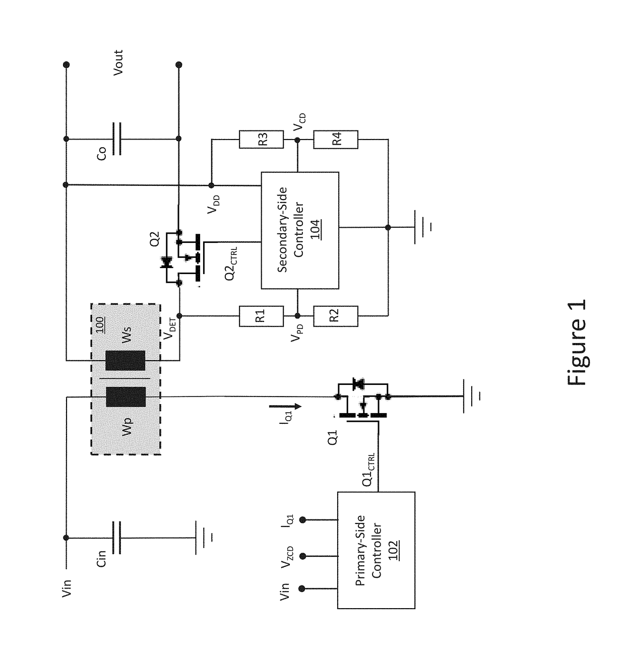
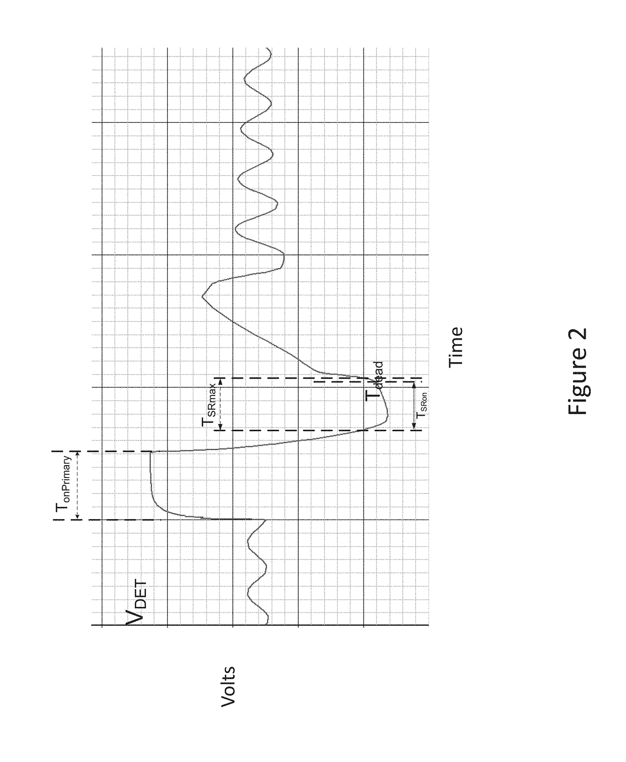
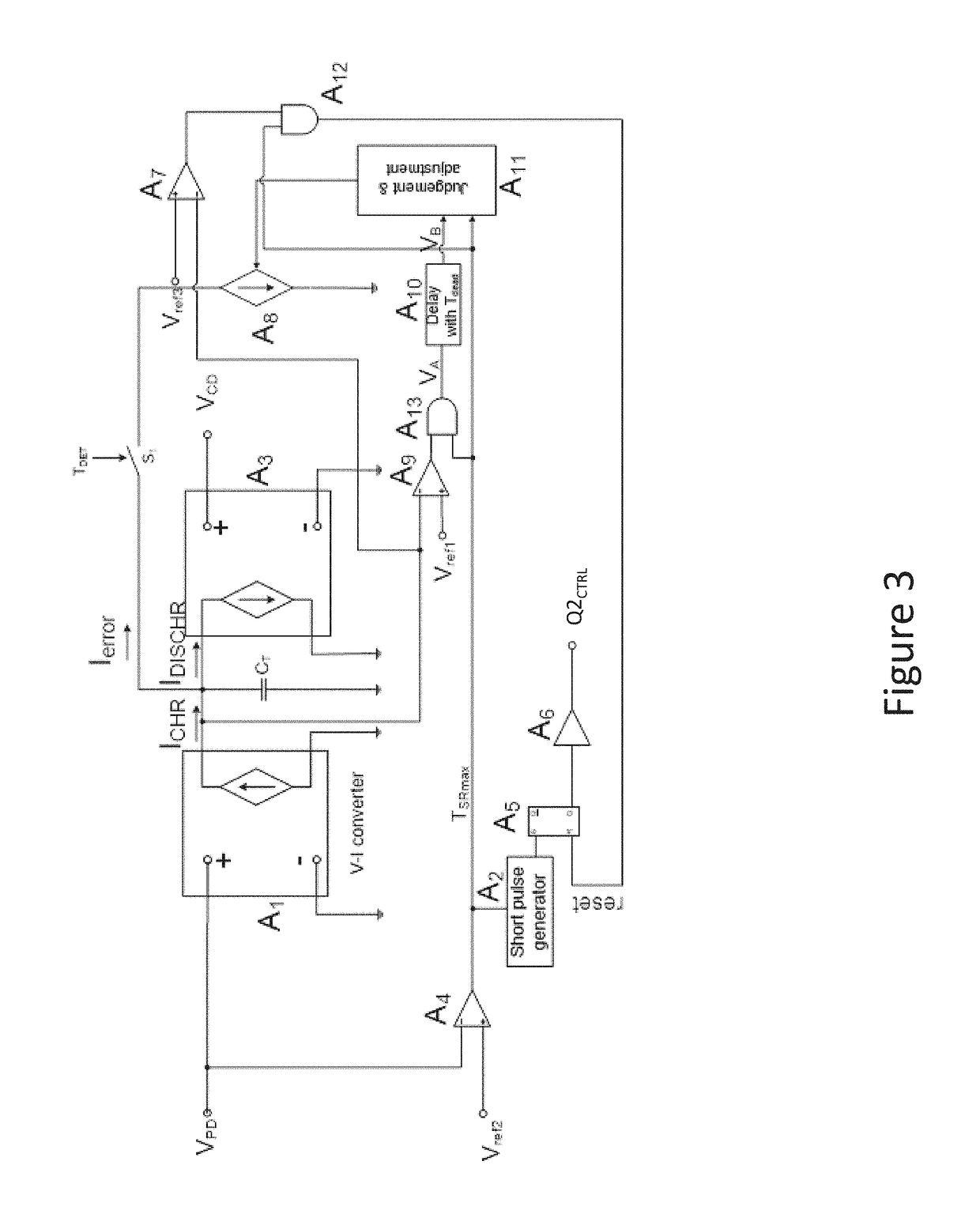
[0015]The embodiments described herein compensate for the settling time portion of the primary-side switch of a flyback converter, and use this compensation to adjust the on-time period of the secondary-side SR switch. In some embodiments, previous or present sampled input voltage information is used to modify the on-time period of the secondary-side SR switch. In other embodiments, correct input voltage information is obtained from the previous switching cycle (settled voltage) and the turn-off time of the SR switch on the secondary side is optimized for the next cycle based on this information. In general, the primary-side switch is controlled to store energy in the flyback transformer during ON periods of the primary-side switch. The secondary-side switch is switched synchronously with switching off the primary-side switch to transfer energy from the transformer to the secondary side of the flyback converter. The off time of the secondary-side switch, which occurs at the end of t...


PUM


Abstract

A flyback converter includes a primary-side switch connected to a primary-side winding of a transformer and a secondary-side switch connected to a secondary-side winding of the transformer. The flyback converter is operated by controlling the primary-side switch to store energy in the transformer during ON periods of the primary-side switch, switching on the secondary-side switch synchronously with switching off the primary-side switch to transfer energy from the transformer to the secondary side, determining an off time of the secondary-side switch based on a reflected input voltage measured at the secondary-side winding when the primary-side switch is on, accounting for a settling time of the reflected input voltage when determining the off time of the secondary-side switch so that the settling time has little or no effect on the off time, and switching off the secondary-side switch based on the off time.

Description

TECHNICAL FIELD[0001]The present application relates to flyback converters, in particular synchronous rectification control for flyback converters.BACKGROUND[0002]A flyback converter is a transformer-isolated converter based on the basic buck-boost topology. In a flyback converter, a switch is connected in series with the transformer primary side. The transformer is used to store energy during ON periods of the primary switch, and provides isolation between the input voltage source and the output voltage. In a steady state of operation, when the primary switch is ON for a period of TON, during the TON period, a diode on the secondary side becomes reverse-biased and the transformer behaves as an inductor. The value of this inductor is equal to the transformer primary magnetizing inductance LM, and the stored magnetizing energy from the input voltage source. As such, the current in the primary transformer (magnetizing current IM) rises linearly from an initial value to a peak value. A...

Claims


Application Information

Patent Timeline
IPC IPC(8): H02M3/335
CPCH02M3/33592H02M3/33576Y02B70/10
Inventor GONG, XIAOWUFAHLENKAMP, MARCSANDERS, ANTHONY
Owner INFINEON TECH AUSTRIA AG
Why Eureka
Eureka Blog
Learn More