

Deposition of Molybdenum Thin Films Using A Molybdenum Carbonyl Precursor
a molybdenum carbonyl and precursor technology, applied in chemical vapor deposition coating, metal material coating process, coating, etc., can solve the problems of difficult control of deposited film thickness, and many current molybdenum complexes for use in cvd and ald do not provide the performance required to implement new processes, etc., to achieve the effect of thin film deposition
- Summary
- Abstract
- Description
- Claims
- Application Information
AI Technical Summary
Benefits of technology
Problems solved by technology
Method used
Image


Examples
example 1
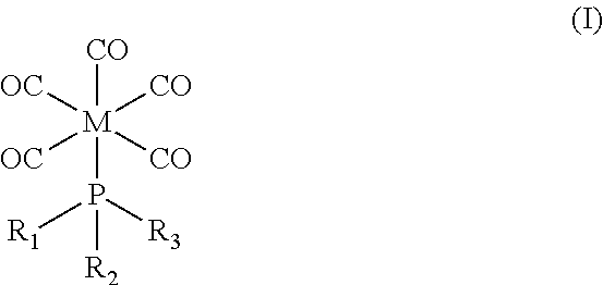
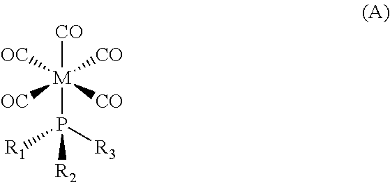
[0076][CH3(Cl)2P]Mo(CO)5 was delivered into a CVD reactor using 25 sccm of nitrogen as the carrier gas, and pulsed for ˜2 seconds followed by a ˜28 second purge. The molybdenum was deposited at ˜400° C. for 8 cycles. The film was cooled down in the reactor to ˜40° C. under vacuum with nitrogen purge before unloading. Film thickness in the range of 180-600 Å and resistivity in the range of 230-400 μΩ·cm were obtained. SEM showed a smooth film with fine grains. XPS analysis confirmed the existence of Mo metal with N and MoOx contaminants on the top surface, which was removed during XPS analysis, and only ˜1.7% C and ˜0.9% P remaining in the film after 300 seconds of sputtering.
example 2
[0077][CH3(Cl )2P]Mo(CO)5 was delivered into a CVD reactor using 10-30 sccm of hydrogen as the carrier gas and reducing agent, and pulsed for ˜2 seconds followed by a ˜58 second purge, and deposited at ˜400° C. at 0.10 to 2.0 Torr for 15-50 pulses. Samples were either cooled down without annealing to ˜40° C. under vacuum with hydrogen purge before unloading, or annealed in-situ at 400° C. in 2 Torr H2 for 30 minutes. Measured film thickness at various points ranged from 80-500 Å with resistivity in the range of 170-300 μΩ·cm. The resistivity was generally less dependent on film thickness. SEM showed a smooth film with fine grains. XPS analysis confirmed the existence of Mo metal with N and MoOx contaminants on top surface only, and ˜3.4% C but no P remaining in the film after 300 seconds of sputtering.
[0078]Examples 3 & 4 below both involve growing molybdenum thin films with [CH3(Cl)2P]Mo(CO)5 using a shower-head deposition tool. When depositing films by pulsed CVD, the temperature ...
example 3
Molybdenum Film Growth with (Methylphosphonous Dichloride)Pentacarbonyl Molybdenum at 330° C. and 1.3 Torr
[0079]The film was grown in a shower-head deposition tool with a working pressure of 1.3 Torr. The bubbler was kept at 33° C., and the nitrogen (carrier gas) flow through the bubbler was 5 sccm. The patterned coupon was kept at 330° C. The film was grown by repeating 14 times the following cycle:[0080]a) Flow the [CH3(Cl)2P]Mo(CO)5 and carrier gas in the deposition chamber for ˜15 seconds.[0081]b) Evacuate the deposition chamber with full vacuum for ˜20 seconds.[0082]c) Purge the deposition chamber with nitrogen (140 sccm) for ˜20 seconds.[0083]d) Evacuate the deposition chamber with full vacuum for ˜20 seconds.[0084]e) Flow the hydrogen (85 sccm) co-reactant in the deposition chamber for ˜240 seconds. The temperature may fluctuate between 315° C. and 345° C. during the hydrogen pulse.[0085]f) Evacuate the deposition chamber with full vacuum for 18 20 seconds.[0086]g) Purge the ...
PUM
| Property | Measurement | Unit |
|---|---|---|
| Temperature | aaaaa | aaaaa |
| Temperature | aaaaa | aaaaa |
| Temperature | aaaaa | aaaaa |
Abstract
Description
Claims
Application Information