System for forming nano-laminate optical coating

a nano-laminate and optical coating technology, applied in the direction of anti-reflective coatings, superimposed coating processes, instruments, etc., can solve the problems of high production cost, poor scratch resistance, and insufficient scratch resistance of cost competitive methods of creating arcs, so as to improve optical coatings, improve optical and mechanical properties, and improve durability and resistance to scratches

Active Publication Date: 2019-01-24
INTEVAC
View PDF0 Cites 12 Cited by
  • Summary
  • Abstract
  • Description
  • Claims
  • Application Information

AI Technical Summary

Benefits of technology

[0010]Disclosed embodiments provide a system specifically designed to form an improved optical coating structure having improved optical and mechanical properties, especially high d

Problems solved by technology

This method offers superior adhesion at inter-layer interfaces and highly accurate control of layers' thicknesses, but requires relatively high production cost.
In this method as well, alternating layers of low and high refractive index are formed, so that the process needs to be repeated leading to relatively weak adhesion at the layer's interface, as compared with the dry method.
One problem with conventional ARC is that most high volume, cost competitive methods of creating ARC's do not create a scratch or wear resistant enough coating to be used on devices t

Method used


Image

  • System for forming nano-laminate optical coating
  • System for forming nano-laminate optical coating
  • System for forming nano-laminate optical coating

Examples


Embodiment Construction

[0024]Embodiments of the inventive system for fabricating optical coating and its processing will now be described with reference to the drawings. Different embodiments or their combinations may be used for different applications or to achieve different benefits. Depending on the outcome sought to be achieved, different features disclosed herein may be utilized partially or to their fullest, alone or in combination with other features, balancing advantages with requirements and constraints. Therefore, certain benefits will be highlighted with reference to different embodiments, but are not limited to the disclosed embodiments. That is, the features disclosed herein are not limited to the embodiment within which they are described, but may be “mixed and matched” with other features and incorporated in other embodiments.

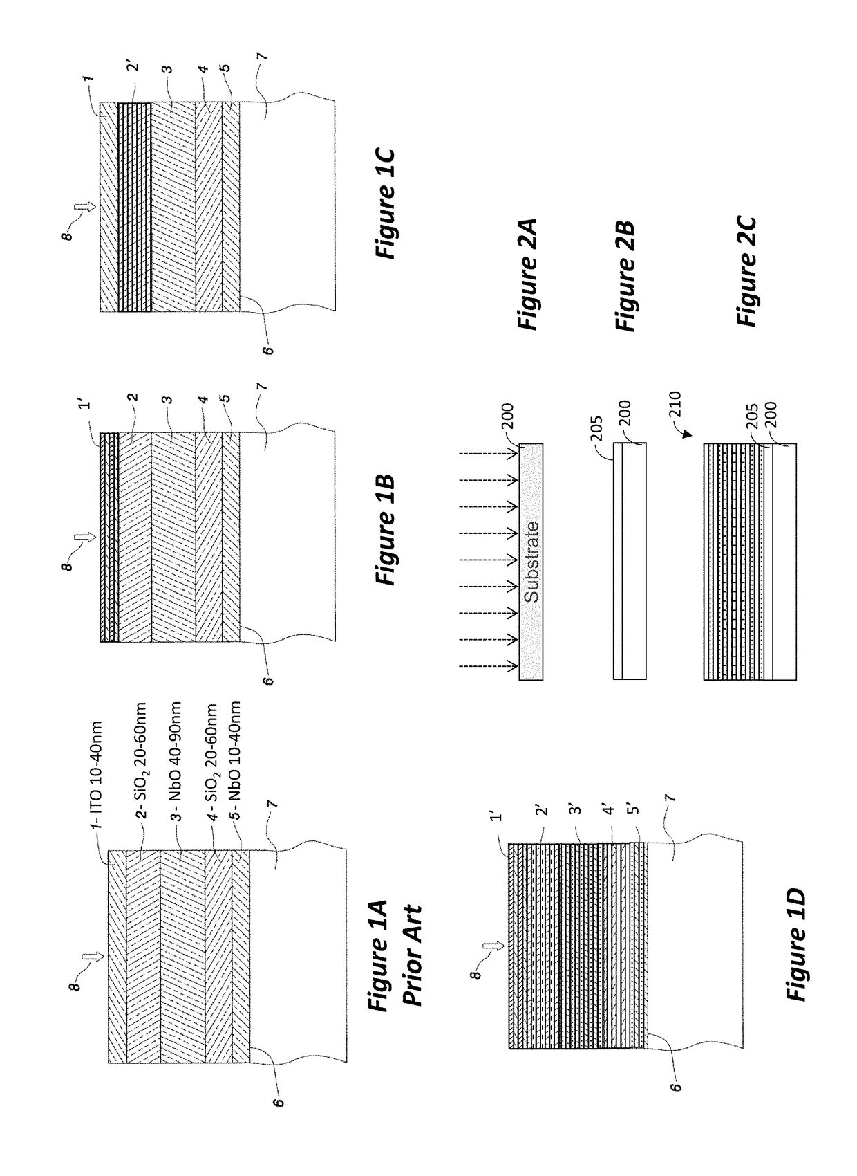
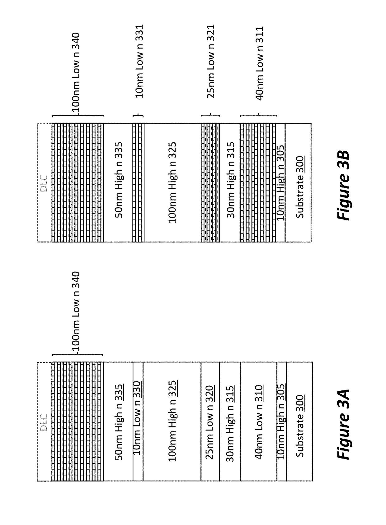
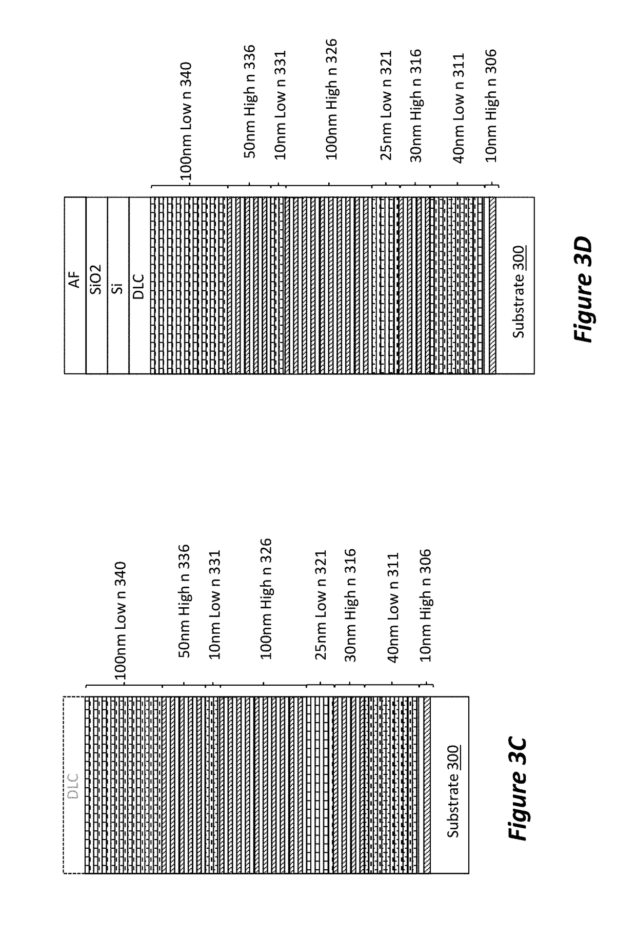
[0025]Disclosed embodiments include systems and methods for forming optical coating having a nano-laminate structure. In the context of this disclosure, the nano-lamin...


PUM

PropertyMeasurementUnit
Thicknessaaaaaaaaaa
Thicknessaaaaaaaaaa
Transport propertiesaaaaaaaaaa

Abstract

A processing system for forming an optical coating on a substrate is provided, wherein the optical coating including an anti-reflective coating and an oleophobic coating, the system comprising: a linear transport processing section configured for processing and transporting substrate carriers individually and one at a time in a linear direction; at least one evaporation processing system positioned in the linear transport processing system, the evaporation processing system configured to form the oleophobic coating; a batch processing section configured to transport substrate carriers in unison about an axis; at least one ion beam assisted deposition processing chamber positioned in the batch processing section, the ion beam assisted deposition processing chamber configured to deposit layer of the anti-reflective coating; a plurality of substrate carriers for mounting substrates; and, means for transferring the substrate carriers between the linear transport processing section and the batch processing section without exposing the substrate carrier to atmosphere.

Description

CROSS-REFERENCE TO RELATED APPLICATIONS[0001]This application claims priority from U.S. Provisional Application No. 62 / 534,438, filed Jul. 19, 2017, and U.S. Provisional Application No. 62 / 651,617, filed Apr. 2, 2018, the disclosures of which are incorporated herein by reference in their entireties.BACKGROUND1. Field[0002]This disclosure relates generally to the field of optical coatings, such as anti-reflective coating, and to the manufacturing of such optical coating.2. Related Art[0003]Anti-reflective coatings (ARC) are used for many applications, such as, e.g., spectacles, plate glass (e.g., car windshield), flat-screen displays, and touch screens. In many of these applications, the requirements on the ARC include efficient anti-reflective property in the visible wavelength, high transparency, and durability. Of course, these properties need to be achieved in a commercially acceptable cost.[0004]In general, there are two methods for forming an ARC on a substrate, a wet and a dry...

Claims


Application Information

Patent Timeline
IPC IPC(8): G02B1/116G02B1/111C03C17/42C03C17/34C08J7/04B32B17/10B05D5/06
CPCG02B1/116G02B1/111C03C17/42C03C17/3482C08J7/045B32B17/10174B05D5/063C03C17/3417C03C17/3441C03C2217/734C03C2217/76C23C14/0052C23C14/0089C23C14/081C23C14/10C23C14/3442C23C14/505C23C14/548G02B1/18G02B1/115C09D5/006C23C14/568C23C14/3464C23C14/566C23C28/44C08J7/0423H01J37/32899
Inventor BLUCK, TERRYBLONIGAN, WENDELL THOMAS
Owner INTEVAC
Why Eureka
Try Eureka