Lidar based on MEMS

Active Publication Date: 2019-02-07
WINDAR PHOTONICS
View PDF2 Cites 7 Cited by
  • Summary
  • Abstract
  • Description
  • Claims
  • Application Information

AI Technical Summary

Benefits of technology

[0006]By the invention as hereby disclosed, it may be possible to easily align the output beam to the optical axis of the beam-focusing optical units, for example by simply changing the selected positions of the reflecting element(s). The selected positions could be based on a desired design, such as a theoretical design, or a proto-type design. Alternatively, the selected positions could be based on a performance parameter of the system as assembled. It should be noted, that by aligning the output beam with the optical axis for the at least one optical element in beam-focusing optical units, it is to be understood, that this is within the precision of for example the MEMS and the determination of the optical axis. Thus, in practice, the alignment with the optical axis is within a certain degree of precision, such that the output beam deviates from the optical axis by such as less than 5 degrees, such as less than 4 degrees, such as less than 3 degrees, such as less than 2 degrees, preferably less than 1 degree and/or more preferably less than 0.1 degrees.
[0007]However, variations of the optical axis from a desired design, known as misalignment, can easily occur, for example during assembly or installation of the beam-focusing optical units. Misalignment may however also occur due to environmental conditions, such as temperature variations, thereby shrinking or expanding the optical elements or other materials, for example holding the optical elements, in the beam-focusing optical units.
[0008]Thus, by the present invention, it may be possible to adapt to the misalignment of the beam-focusing optical units, simply by changing the selected positions of the reflecting element(s). In contrast to typical alignment, the present invention provides alignment, where at least mechanical alignment of the beam-focusing optical units may be avoided. Mechanical alignment may be nice to avoid, especially when the LIDAR system is placed on top of a wind turbine, where it is difficult to perform mechanically alignment. Even if the beam-focusing optical units could be uninstalled from the top of the wind-turbine and be mechanically aligned at ground, there would still be a risk of misaligning the beam-focusing optical units when the LIDAR system is being installed again on top of the wind-turbine. Thus, the present invention provides a LIDAR system that can be aligned with low risk, for example by changing the selected positions remotel

Problems solved by technology

However, variations of the optical axis from a desired design, known as misalignment, can easily occur, for example during assembly or installation of the beam-focusing optical units.
Misalignment may however also occur due to environmental conditions, such as temperature variations, thereby shrinking or expanding the optical elements or other materials, for example holding the optical elements, in the beam-focusing optical units.
Mechanic

Method used


Image

  • Lidar based on MEMS
  • Lidar based on MEMS
  • Lidar based on MEMS

Examples


Example

EXAMPLE 1

A Generalized LIDAR System

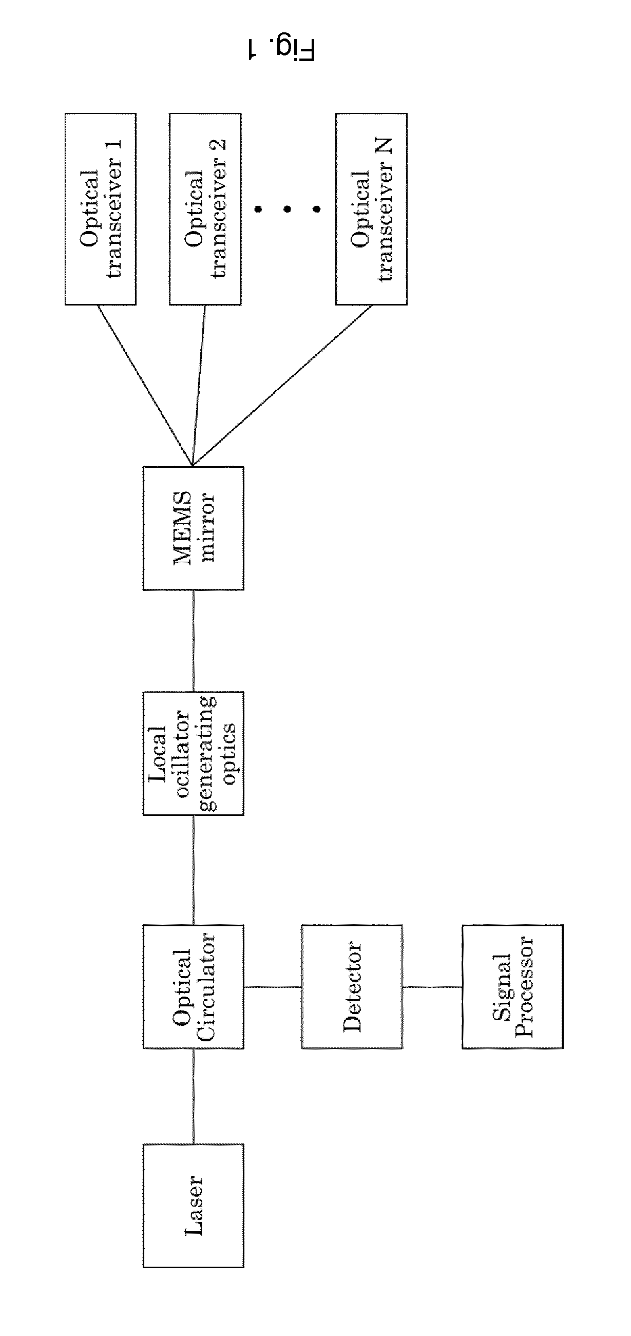
[0058]FIG. 1 shows an embodiment of the LIDAR system according to the present invention. A laser is optically connected to an optical circulator via a first port. The circulator comprises three ports, and a second port is optically connected to the local oscillator generating optics. The local oscillator generating optics is further optically coupled to a MEMS mirror, which is configured such that it is able to direct light coming from the laser, through the optical circulator, through the local oscillator generating optics, into one of the plurality of beam-focusing optical units, here denoted as optical transceivers. The optical transceivers are configured for receiving backscattered light from a target, such that the backscattered light is able to be directed back into the MEMS mirrors, through the local oscillator generating optics, from which there is a reflected reference beam, which is superpositioned with the backscattered light, into the o...

Example

EXAMPLE 2

A LIDAR System Showing Two Beam-Focusing Optical Units with Optical Elements on a Straight Optical Axis

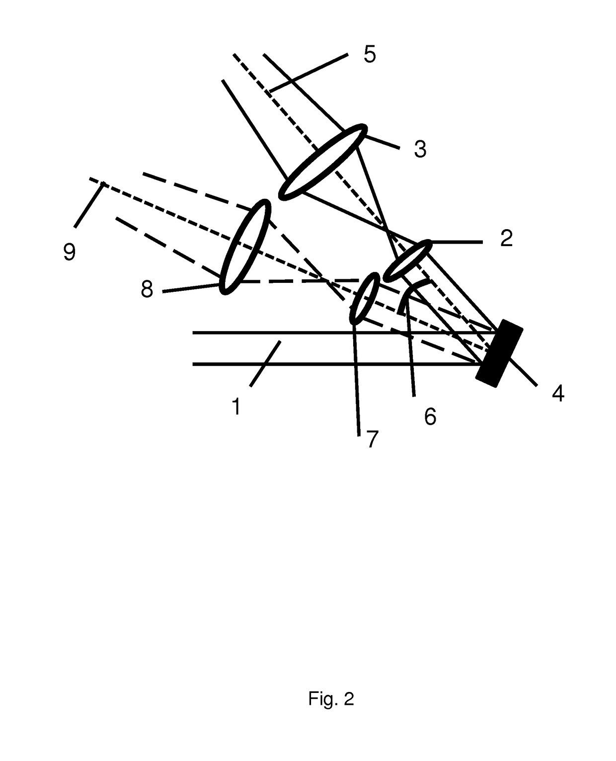
[0059]FIG. 2 shows an embodiment of the LIDAR system according to the present invention. An output beam 1 is propagating from a beam-generating section (not shown in this figure) towards a MEMS 4, having a reflective element, such that the output beam is redirected between two beam focusing optical units, in this example having two optical elements, in this example a first lens 2 and a second lens 3 in the first beam-focusing optical unit, and a first lens 7 and a second lens 8 in the second beam-focusing optical unit. The MEMS 4 is configured for being tilted at an angle 6 in order to align the output beam to the optical axes for the two optical elements in the beam-focusing optical units. The first beam-focusing optical unit has an optical axis 5, which is the rotationally symmetric axis of the beam-focusing optical unit, and in this case the optical axis coincides with ...

Example

EXAMPLE 3

A LIDAR System Showing Two Beam-Focusing Optical Units with Optical Elements on a Straight Optical Axis

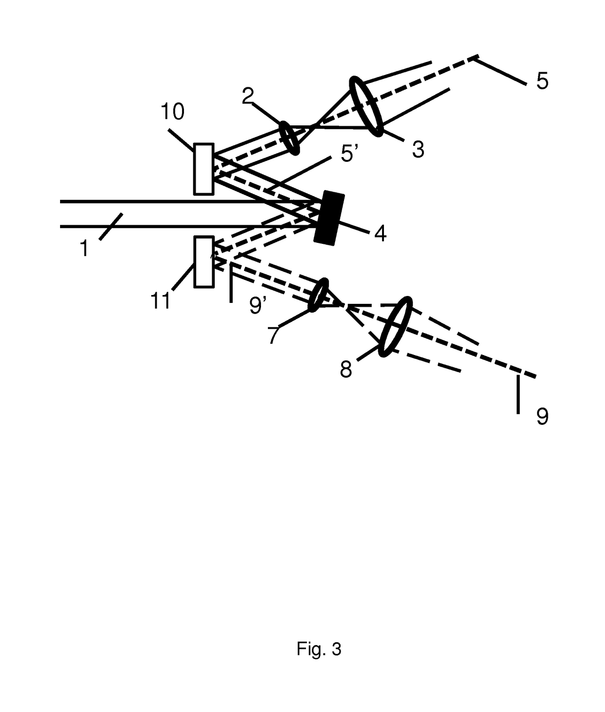
[0060]FIG. 3 shows an embodiment of the LIDAR system according to the present invention. An output beam 1 is propagating from a beam-generating section (not shown in this figure) towards a MEMS 4, having a reflective element, such that the output beam is redirected between two beam focusing optical units, in this example having two optical elements, in this example a first lens 2 and a second lens 3 in the first beam-focusing optical unit, and a first lens 7 and a second lens 8 in the second beam-focusing optical unit. The MEMS 4 is configured for being tilted at an angle in order to align the output beam to the optical axes for the two optical elements in the beam-focusing optical units. The first beam-focusing optical unit has an optical axis 5, which is the rotationally symmetric axis of the beam-focusing optical unit, and in this case the optical axis coincides with th...


PUM


Abstract

A system for measuring velocity of particles such as particles in air is a Light Detection and Ranging (LIDAR) system, having a micro-electro-mechanical-system (MEMS).

Description

FIELD OF INVENTION[0001]The present invention relates to a system for measuring velocity of particles such as particles in air. The present invention relates in particular to a Light Detection and Ranging (LIDAR) system, having a micro-electro-mechanical-system (MEMS).BACKGROUND OF INVENTION[0002]It is well-known that LIDAR can be used for measuring a velocity of a particle. Typically, a single beam-focusing optical unit, such as a telescope, is used for measuring the velocity. The single telescope is typically both used as a transmitter and a receiver of light, the light typically being a laser beam. First, light is transmitted to a target via the telescope, secondly, light is scattered at the target, and finally, backscattered light is received via the telescope, such that a velocity component can be determined.[0003]A LIDAR system having a single telescope is limited to line of sight measurement, prohibiting the determination of, for example, a wind field having multiple velocity...

Claims


Application Information

Patent Timeline
IPC IPC(8): G01S17/95G01S7/481G01S17/58G02B26/08
CPCG01S17/95G01S7/4812G01S7/4817G01S17/58G02B26/0833Y02A90/10
Inventor KORSGAARD JENSEN, JORGENRODRIGO, PETER JOHNPEDERSEN, CHRISTIANHU, QI
Owner WINDAR PHOTONICS
Why Eureka
Try Eureka