Circular x-ray tube and an x-ray instrument comprising the circular x-ray tube

a technology of circular x-ray tube and x-ray instrument, which is applied in the direction of x-ray tubes, x-ray tubes with very high current, x-ray tubes, etc., can solve the problems of in-situ deployment of such x-ray tubes, x-ray tubes must be connected to a source of high electric voltage, and reduce the legibility of images, and the effect of negative impact on the x-ray scanning of objects

Active Publication Date: 2019-02-07
RADALYTICA SRO
View PDF16 Cites 2 Cited by
  • Summary
  • Abstract
  • Description
  • Claims
  • Application Information

AI Technical Summary

Benefits of technology

[0022]The X-ray instrument can be used for the acquisition of X-ray images of the object from any position within the full range of 360°. The prerequisite is that the detector is aligned behind the region for the positioning of the irradiated object and that the impact detection surface faces the region for the positioning of the irradiated object. The X-ray instrument allows an extensive set of images for the modelling of the object internal structure to be acquired. The X-ray beam spreads in all directions and therefore it is possible to arrange the detector either under or above the space delimited by the circular body. Preferably, X-radiation can be used for the X-ray laminography of a planar irradiated object.
[0023]In a preferred embodiment of the X-ray instrument according to the invention at least three detectors are arranged to form a polygonal detection field substantially copying a circular ground plan. The number of detectors forming the detection field affects the degree of the polygon. If the number of used detectors is small, there are gaps between individual detectors and the impact detection surfaces of the neighbouring detectors form a distinctive angle. The advantage of the detection field is the fact that it is no...

Problems solved by technology

The disadvantages of standard X-ray tubes rest in the fact that the X-ray tubes must be connected to a source of high electric voltage.
“In-situ” deployment of such X-ray tubes is considerably limited by this fact.
Among other disadvantages is rather expensive manufacture and the fact that X-ray tubes are sensitive to rough handling that cannot always be eliminated in the field operations.
Common disadvantage of the aforementioned known X-ray tubes include the fact that if an object is put into the line of X-radiation, only one side the object is irradiated.
The need to move the X-ray tube—detector pair is demanding and requires expensive mechanical solutions.
This reduces the speed of measurement and, moreover, the movement of the object or the X-ray tube introduces inaccuracies in the set of X-ray images that need to be compensated or otherwise compromise the quality of the resulting three-dimensional model.
Although the aforementioned invention successfully resolves the rotational movement of the X-ray tube or the object, its dis...

Method used


Image

  • Circular x-ray tube and an x-ray instrument comprising the circular x-ray tube
  • Circular x-ray tube and an x-ray instrument comprising the circular x-ray tube
  • Circular x-ray tube and an x-ray instrument comprising the circular x-ray tube

Examples


example 1

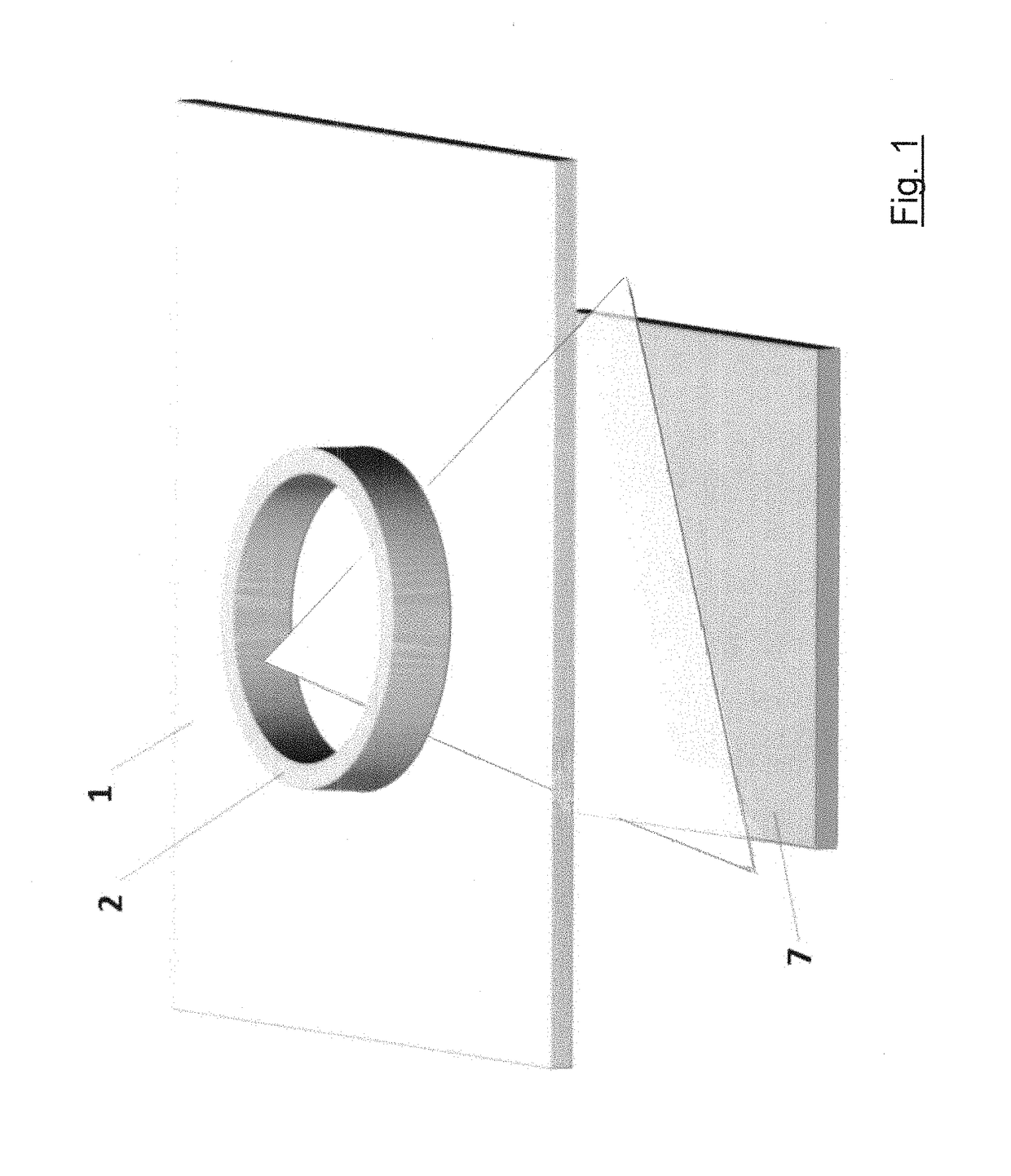
[0050]FIG. 1 shows a schematic diagram of an example of the application of the X-ray instrument with the circular X-ray tube that can be used for X-ray laminography. The planar irradiated object 1, for example a composite plate, is positioned under the circular X-ray tube, of which only the circular body 2 is visible in the schematic diagram. The circular X-ray tube emits an X-ray beam striking upon the irradiated object 1. Under the object 1, an imaging detector 7 of ionizing radiation, whose impact detection surface is struck upon by the X-ray beam penetrating the object 1, is provided. The imaging detector 7 can be, for example, the model known under the TimePix brand.

[0051]The X-ray beam is gradually radiated within the full range of 360°, allowed by the circular X-ray tube, which results in the X-radiation passage through the exposed part of the irradiated object 1. The result of X-ray laminography is evaluated from a set of acquired images in a way known to a person skilled in...

example 2

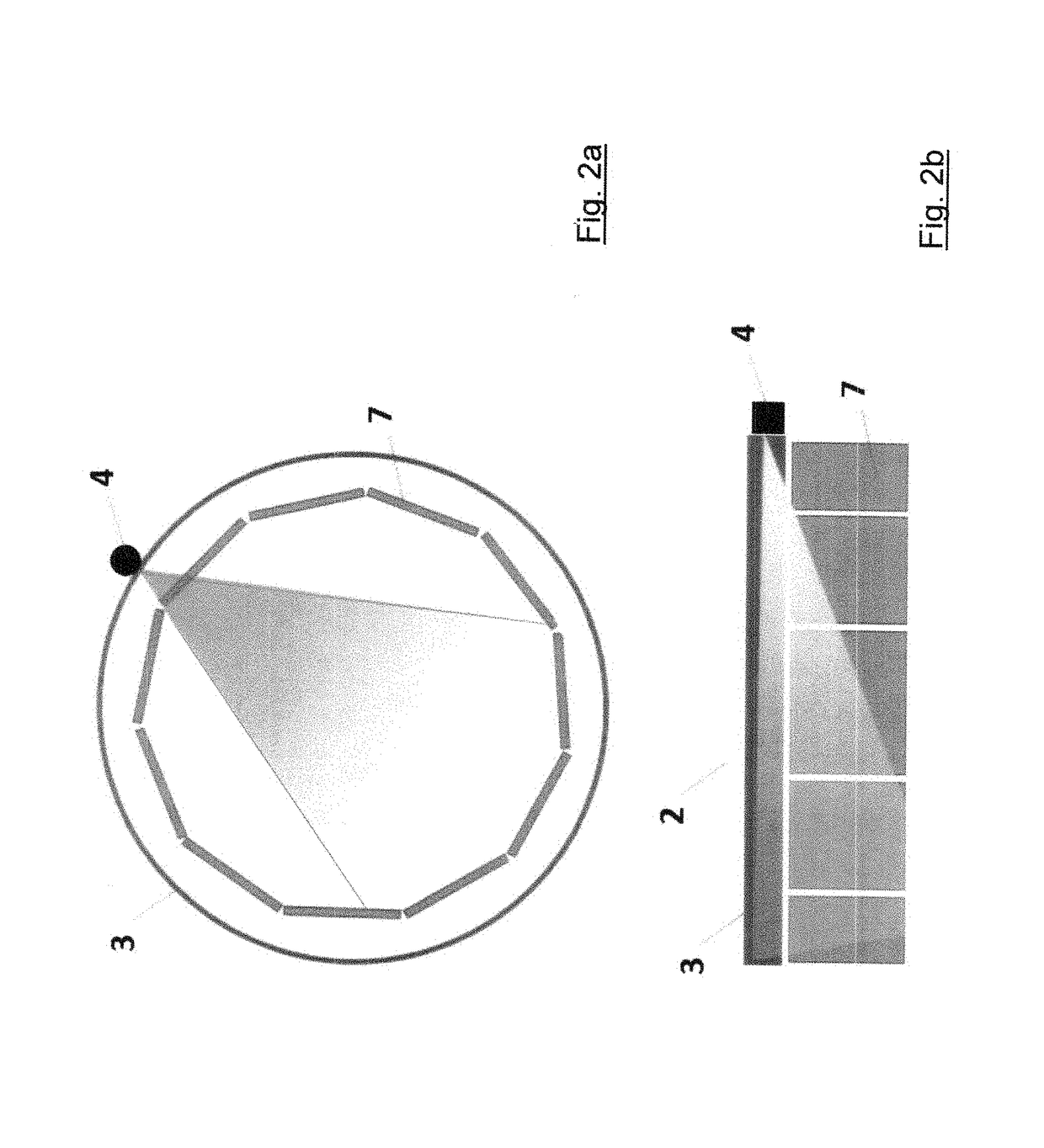
[0052]FIG. 2a and FIG. 2b provide a schematic diagram of an example of the embodiment of the X-ray instrument with the circular X-ray tube with an unshielded X-ray beam. For better clarity of the figures, the circular body 2 is not provided. The circumferential element 3, comprised by e.g. a piece of plastic material, is supported by the circular body 2, or, where applicable, is integrated in the circular body 2. One pressure element 4 manufactured from e.g. tungsten is dragged upon the circumferential element 3. Eleven detectors 7 form a polygonal circular detection field without gaps that allows, with the rotating pressure element 4, eleven direct X-ray images per one revolution of the circular body 2 to be acquired. The detection field is arranged under the space delimited by the circular body 2, as shown in FIG. 2b. The detectors 7 can be tilted with regard to the X-ray beam to improve the X-radiation incidence onto their impact detection surface.

[0053]In a modified Example 2, n...

example 3

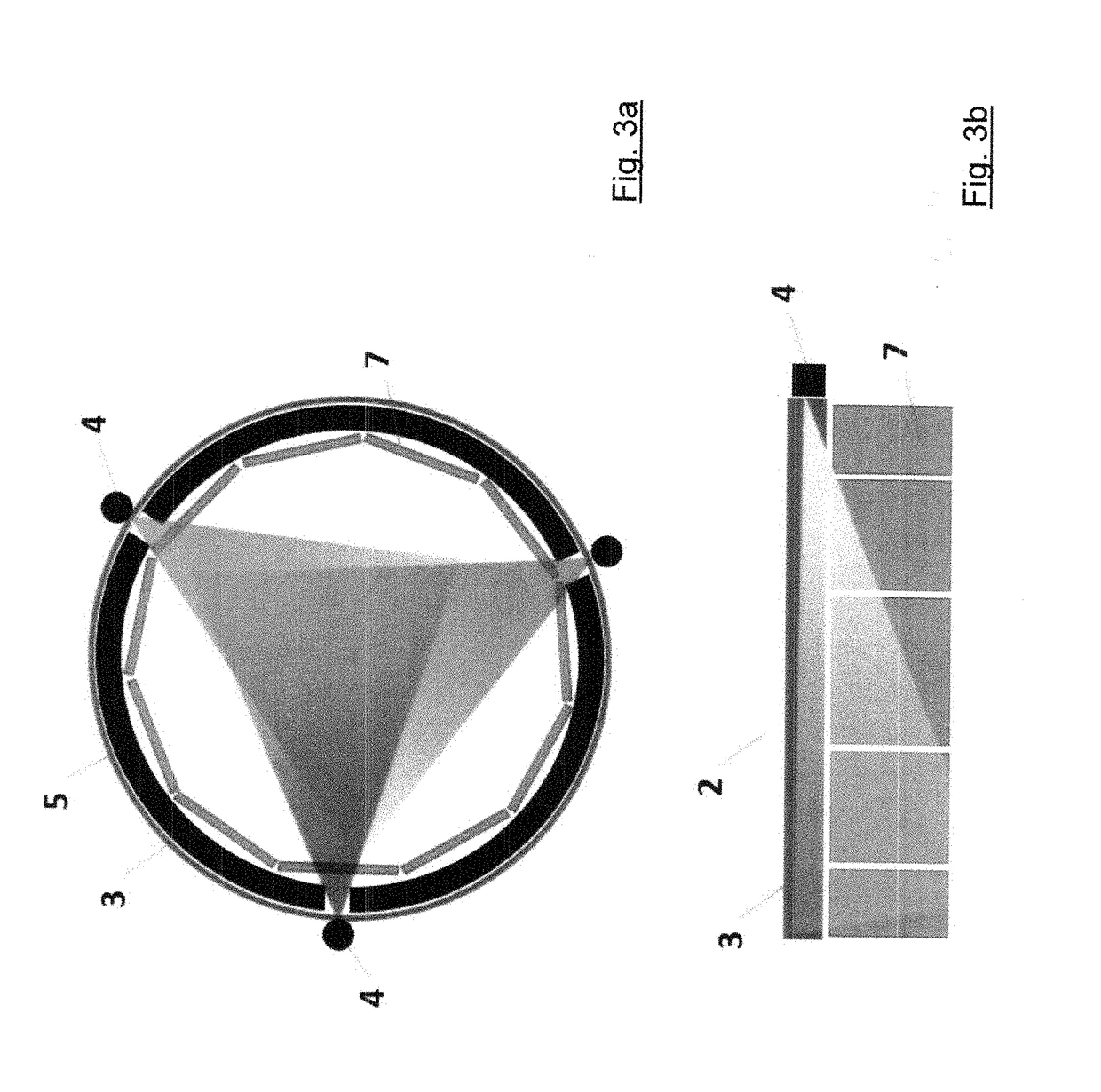
[0054]FIG. 3a and FIG. 3b provide a schematic diagram of an example of the embodiment of the X-ray instrument with the circular X-ray tube with an X-ray beam collimated by a shield 5. For better clarity of the figures, the circular body 2 is not provided but only the shield 5 is provided in the figure. The shield 5 is comprised of for example lead. The schematic diagram shows three openings in the shield 5 that collimate X-ray beams from three neighbouring pressure elements 4. The pressure elements 4 have regular distances from one another. The detectors 7 are employed similarly as in Example 2.

[0055]The shield 5 rotates together with the rotating pressure elements 4, so that the openings in the shield 5 correspond with the pressure elements 4. The collimation of X-ray beams eliminates X-ray image distortion.


PUM


Abstract

The circular X-ray tube for the irradiation of the object (1) by X-radiation comprising the circular body (2) and at least two friction elements that rub together whereby forming a triboluminescent source of X-radiation. The one friction element comprises at least one circumferential element (3) arranged on the external circumferential side of the circular body (2) of the X-ray tube and the other friction element comprises at least one pressure element (4) that is pressed against the circumferential element (3), where the pressure element (4) is adapted for dragging upon the circumferential element (3), and/or at least one circumferential element (3) is adapted for pulling through under the pressure element (4). The X-ray instrument utilizes the circular X-ray tube and the imaging detectors (7) of ionizing radiation.

Description

FIELD OF THE INVENTION[0001]The invention concerns circular X-ray tubes for the generation of X-radiation and an X-ray instrument fitted with the circular X-ray tube to acquire X-ray images.BACKGROUND OF THE INVENTION[0002]X-radiation is a type of electromagnetic radiation that is generated by interactions of high energy electrons. Interactions of high energy electrons can be found in a natural environment or can be initiated artificially. Instruments purposefully used for X-radiation generating are generally called X-ray tubes.[0003]While the release of energy in the form of X-radiation during an interaction of high energy electrons follows the laws of nature, the principle, based on which high energy electrons are prepared for the interaction in individual X-ray tubes, may differ.[0004]Known X-ray tubes comprise electricity-powered X-ray tubes. This X-ray tube in its simplest version includes two electrodes, the cathode and the anode, that are installed in an air-tight glass bulb ...

Claims


Application Information

Patent Timeline
IPC IPC(8): H05G2/00G01N23/044
CPCH05G2/00G01N23/044G01N2223/309G01N2223/308H01J35/02H01J2235/06H01J35/06
Inventor KADERABEK, RICHARDUHER, JOSEF
Owner RADALYTICA SRO
Why Eureka
Try Eureka