Motor drive device that reduces collision noise of moving member, method of controlling same, and storage medium

a technology of motor drive and moving member, which is applied in the direction of dynamo-electric converter control, television system, dynamo-electric gear control, etc., can solve the problems of collision noise, impact vibration, and lower efficiency of stepping motor than a brushless motor and a dc motor, and achieve the effect of reducing collision nois

Inactive Publication Date: 2019-02-14
CANON KK
View PDF0 Cites 7 Cited by
  • Summary
  • Abstract
  • Description
  • Claims
  • Application Information

AI Technical Summary

Benefits of technology

[0014]The present invention provides a motor drive device that is capable of reducing collision noise generated by a mirror while maintaining a driving speed of the mirror, a method of controlling the same, and a storage medium.
[0018]According to the present invention, it is possible to reduce the collision noise generated by the moving member while maintaining the driving speed of the moving member, such as a mirror.

Problems solved by technology

However, in a case where the stepping motor is rotated at a high speed and a case where the load on the motor is high, the motor sometimes steps out, and further, in a case where the rotational acceleration of a rotor undergoes a sudden change, impact vibration is caused due to the rotational inertia of the rotor.
Further, the stepping motor is lower in efficiency than a brushless motor and a DC motor.
However, if the method described in Japanese Laid-Open Patent Publication (Kokai) No. 2011-97720 is applied to a mirror drive device that drives a main mirror using a motor as a drive source, there occurs the following problem: In a mechanism, for example, which brings the main mirror being rotated into abutment with a stopper while performing deceleration driving of the main mirror, and holds the main mirror at a fixed stop position while pressing a mirror mechanism against the stopper, collision noise is generated when the main mirror is brought into abutment with the stopper.
Further, if the load of the main mirror changes due to the posture or position of the mirror mechanism and the temperature environment, the load on the motor increases, so that the main mirror sometimes stops before reaching a predetermined position.
However, the load of the main mirror changes due to the posture or position of the mirror mechanism and the temperature environment, which varies the load on the motor, and hence it is difficult to bring the main mirror into abutment with the stopper at the predetermined speed.
Further, if the main mirror is excessively decelerated, variation of the load of the main mirror due to the posture or position of the mirror mechanism and the temperature environment increases the load on the motor, so that the main mirror sometimes stops before reaching the predetermined position.

Method used


Image

  • Motor drive device that reduces collision noise of moving member, method of controlling same, and storage medium
  • Motor drive device that reduces collision noise of moving member, method of controlling same, and storage medium
  • Motor drive device that reduces collision noise of moving member, method of controlling same, and storage medium

Examples


first embodiment

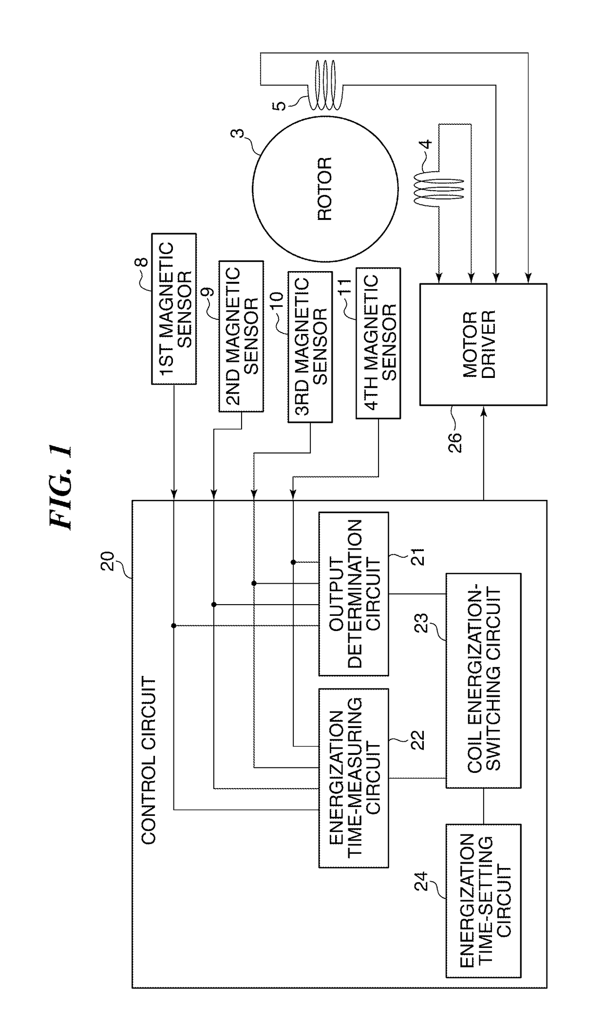
[0043]FIG. 1 is a block diagram of a motor drive device according to the present invention and a motor.

[0044]The illustrated motor drive device includes a control circuit 20, and the control circuit 20 includes an output determination circuit 21, an energization time-measuring circuit 22, a coil energization-switching circuit 23, and an energization time-setting circuit 24.

[0045]As described hereinafter, the motor is provided with first to fourth magnetic sensors (detection sensors) 8 to 11, and the first to fourth magnetic sensors 8 to 11 each output a voltage according to rotation of a rotor 3. In the illustrated example, for example, Hall elements are used for the first to fourth magnetic sensors 8 to 11.

[0046]The output determination circuit 21 is connected to the first to fourth magnetic sensors 8 to 11, and determines an output state of each of the first to fourth magnetic sensors 8 to 11. The energization time-measuring circuit 22 is connected to the first to fourth magnetic ...

second embodiment

[0151]Next, a description will be given of a motor drive device according to the present invention.

[0152]FIG. 10 is a block diagram of the motor drive device according to the second embodiment of the present invention and a motor. The same components in FIG. 10 as those in FIG. 1 are denoted by the same reference numerals, and description thereof is omitted.

[0153]In the illustrated motor drive device, the control circuit 20 includes an energization time-storing circuit 25 in place of the energization time-setting circuit 24, and the energization time-storing circuit 25 is connected to the first to fourth magnetic sensors 8 to 11 and the coil energization-switching circuit 23. The energization time-storing circuit 25 stores a time period (elapsed time) taken for an output from each of the first to fourth magnetic sensors 8 to 11 to switch.

[0154]For example, the energization time-storing circuit 25 records an energization time period having elapsed after the switching of a voltage out...


PUM


Abstract

A motor drive device that is capable of reducing collision noise generated by a mirror while maintaining a driving speed of the mirror. A control circuit of the motor drive device controls driving of a motor including magnetic sensors for detecting a rotational position of a rotor. An energization time-setting circuit of the control circuit sets an energization time period of the motor, and the control circuit controls driving of the motor depending on a detection result output from each magnetic sensor and the set energization time period.

Description

BACKGROUND OF THE INVENTIONField of the Invention[0001]The present invention relates to a motor drive device, a method of controlling the same, and a storage medium, and more particularly to driving of a mirror equipped in a single-lens reflex camera.Description of the Related Art[0002]In general, a stepping motor has the features of compactness, high torque, and a long product life, and is capable of easily performing a positioning operation by open-loop control. Therefore, the stepping motor is widely used for information home electrical appliances, such as a camera and an optical disk device, OA equipment, such as a printer and a projector, and so forth.[0003]However, in a case where the stepping motor is rotated at a high speed and a case where the load on the motor is high, the motor sometimes steps out, and further, in a case where the rotational acceleration of a rotor undergoes a sudden change, impact vibration is caused due to the rotational inertia of the rotor. Further, t...

Claims


Application Information

Patent Timeline
Patent Type & Authority Applications(United States)
IPC IPC(8): H04N5/232H02P8/14H02K37/14H02K11/215H02P21/06H04N5/225
CPCH04N5/2328H02P8/14H02K37/14H02K11/215H02P21/06H04N5/2254H04N5/23299G03B19/12H02P6/16H02P8/38G03B2205/0069H04N23/55H04N23/60H04N23/685H04N23/695
Inventor SUTO, KAORUAOSHIMA, CHIKARAKOJIMA, NOBUHISA
Owner CANON KK
Why Eureka
Try Eureka