
Smart bed

a smart bed and bedside technology, applied in the field of smart beds, can solve the problems of decubitus ulcers or bed sores, painful and very slow healing, and difficult to avoid bacterial infections

Inactive Publication Date: 2019-02-21
TORRES EVELYN
View PDF0 Cites 5 Cited by
  • Summary
  • Abstract
  • Description
  • Claims
  • Application Information

AI Technical Summary

Benefits of technology

This device is designed to help care for patients who spend a lot of time in bed. It can prevent new bed sores from forming, reduce the intensity of existing ones, and promote healing of existing ones.

Problems solved by technology

One of the most common problems in the care of long-term bedridden patients is the development of decubitus ulcers or bed sores.
Once this ulcer forms it is quite painful and very slow to heal.
Bacterial infections are difficult to avoid and frequently prolong the healing process.
Furthermore, the bedridden patient may unconsciously favor resting on body surfaces that have recovering wounds resulting, e.g., from surgery, accident or other trauma.
No matter what the cause, when air / oxygen is prevented from reaching the skin of a body part, and when normal perspiration is prevented for a prolonged period, the result is non-optimal healing and possible infection of an existing wound, or, in the case of no wound at the outset, the formation of bed sores.
In extreme cases, an undiagnosed, untreated, or inadequately treated bedsore can lead to osteomyelitis, septicemia, and even death.
However, because of the materials used, or the configurations developed, or the expense of making and using the more elaborate devices, there has been no completely satisfactory solution to the problem.
Several factors play an important role in the development bed sores, including continuous contact between the patient and the bedding material that leads to moisture accumulation, lack of air flow to the skin, compression of soft tissues resulting in stagnating blood flow, and inadequate supervision of the patient by care givers.
Many of the aforementioned solutions suffer from one or more drawbacks, such as: mechanical complexity leading to high cost or frequent break-down and maintenance, a need for constant supervision by the care provider to detect the presence or development of bed sores, undesirable restraint of a patient's free movement, or ineffectiveness due to failure to address multiple factors at play.
Such a device suffers from the drawbacks that it is a complicated device which must be built into a bed or anchored to it in such a manner as requiring careful expertise, and that is requires constant supervision so that the relief of pressure in one area does not unduly create pressure in another area of the patient's body.
Thus, there remains an urgent need, for a bed sore prevention apparatus that is relatively inexpensive, uncomplicated, and effective.

Method used


Image

  • Smart bed
  • Smart bed

Examples


example 1

Exemplary Design of Smart Sheet Mattress Overlay

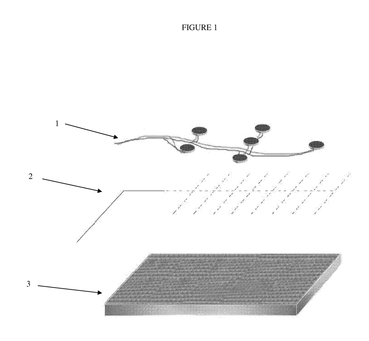
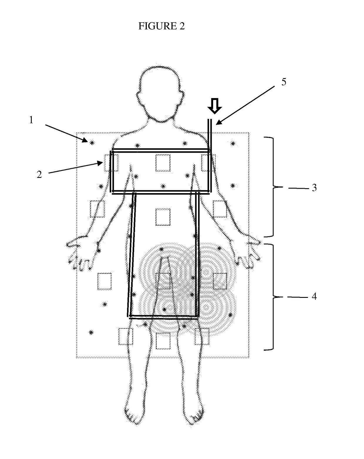
[0079]A two-zone mattress overlay is constructed using 27 vibrational motors, 12 pressure sensors and one temperature sensor. FIG. 2 shows the arrangement of the motors and sensors, which lie in a single layer between sheets of fabric. In a second layer, below this first layer, lies the perforated airflow manifold, which is designed as a double-loop arrangement. This arrangement provides effect airflow to all areas of a patient's body. The entire mattress overlay is enclosed in a fabric container which is easily moved from one bed to another, and can also be rolled up for easy storage when not in use. The vibrational motors are medical grade Precision Haptic DC motors operating at 100 Hz frequency.

[0080]Attached via cabling and compressed air hosing to the mattress overlay is the control unit. The control unit is centered on an Arduino Mega 2560 microprocessor, which controls all aspects of the device's operation. The user interface is...

example 2

Effect of Underlying pressure-redistibuting gel layer

[0081]The mattress overlay of Example 1 is operated with a human patient lying in a supine position either with or without an air-permeable, hydrophobic gel layer six-inches in thickness underneath the mattress overlay. The pressure exerted by the patient on the mattress overlay is recorded by nine pressure sensors over a period of about 200 seconds. It is found that in the absence of the gel layer, only 8 of the pressure sensors show a force exerted of under 5 Newtons. One sensor, however, consistently shows a force exerted of from 10 to 45 Newtons. This is considerably higher than is desirable, and would suggest a higher risk of bed sore development for a patient lying supine on such a mattress. In contrast, when the mattress overlay is used on top of the hydrophobic gel, sensor 8 shows a consistent force exerted of only about 8 Newtons, while the remaining sensors all register below 5 Newtons. This demonstrates that the gel lay...

example 3

Effect of Airflow Manifold

[0082]The design of Example 1 utilizes a double-rectangular loop airflow manifold as shown in FIG. 2. Perforations are placed around the length of the tubing (diameter ¼ inch) approximately every five inches. Compressed air is supplied at a pressure of 60 psi, and the airflow was turned on for two-minute intervals every sixteen minutes, while temperature was recorded at five second intervals. Temperature was measured at the single sensor under the center of the patient's body. The patient did not substantially move for the duration of the 30 minute test. The results demonstrate that absent airflow, the temperature sensor gradually recorded higher temperature as heat and moisture accumulated between the patient's body and the mattress overlay. In contrast, with the intermittent running of the airflow manifold, the temperature sensor's recorded temperature remained approximately constant.


PUM


Abstract

The present disclosure provides a device for use with a bed, chair, or other furniture for seating, reclining, or lying down, which comprises one or more pressure sensors, a perforated air-flow manifold, a plurality of vibrational motors, and a controller unit for the prevention and / or treatment of bed sores in bedridden patients, as well as methods of use thereof.

Description

RELATED APPLICATIONS[0001]This application claims the benefit of U.S. Provisional Application No. 62 / 311,836, filed Mar. 22, 2016, the contents of which are incorporated herein by reference in its entirety.FIELD OF THE INVENTION[0002]This invention relates to the field of devices, such as mattresses, mattress covers and beds, for the prevention and / or treatment of bed sores.BACKGROUND[0003]As Americans live longer, the number of hospitals and nursing homes treating patients for long-term care has increased dramatically. One of the most common problems in the care of long-term bedridden patients is the development of decubitus ulcers or bed sores.[0004]Bed sores are localized areas of cellular necrosis occurring in pressure areas of the patient's body, mainly in bony prominences thereof, and are often caused by constriction of blood flow to capillary vessels due to prolonged localized pressure applied to the body. They result from the pressure exerted on the skin and subcutaneous tis...

Claims


Application Information

Patent Timeline
IPC IPC(8): A61B5/00A61G7/057A61H23/00A61B5/103A61B5/01
CPCA61B5/447A61G7/05784A61H23/00A61B5/1036A61B5/6892A61B5/01A61G2203/34A61G2203/46A61H2201/0146A61H2201/0149A61H2201/1654A61H2201/501A61H2201/5043A61H2201/5061A61H2201/5071A61H2201/5082A61B5/7455A61G7/057A61H23/0254A61H2201/0142A61H2201/50
Inventor TORRES, EVELYN
Owner TORRES EVELYN
Learn More