Feeding process of chlorine fluoride

a technology of chlorine fluoride and fluoride, which is applied in the field of feeding process of chlorine fluoride, can solve the problems of high pressure in the container for transporting gas, large cost of transportation, and gas leakage out and damage to the container, and achieve the effect of stable over a long tim

Active Publication Date: 2019-02-21
KANTO DENKA IND CO LTD
View PDF5 Cites 3 Cited by
  • Summary
  • Abstract
  • Description
  • Claims
  • Application Information

AI Technical Summary

Benefits of technology

[0070]The present invention solves the problems associated with the conventional process of feeding chlorine fluoride from a gas container such as a gas cylinder, and provides a feeding process that can feed chlorine fluoride in a large amount, and stably over a long time.
[0071]The feeding process of chlorine fluoride of the present invention provides the following effects.

Problems solved by technology

However, chlorine fluoride is highly corrosive / toxic, and a compressed gas, so it is difficult to be packed at high pressure in containers for transporting gas, such as a gas cylinder, and be circulated.
This is because corrosion of the container material is promoted by gas packed at high pressure, so that there is danger of gas leaking out and the container being damaged.
Although chlorine fluoride is a useful gas, it cannot be packed in a gas container at high pressure, so the packed amount per container was small, the cost of transportation was large, and the work for exchanging the container increased.
An adoption of a high temperature condition may cause damage to the reactor by corrosion due to the generated fluorine.
Further, hydrogen fluoride used as the starting material, with a boiling point of 19.5° C., can readily liquefy and may cause a serious chemical injury when the solution spatters, so it is dangerous.
Furthermore, generating chlorine fluoride by such an electrolysis method is difficult and not readily achievable.

Method used


Image

  • Feeding process of chlorine fluoride
  • Feeding process of chlorine fluoride
  • Feeding process of chlorine fluoride

Examples


example 1

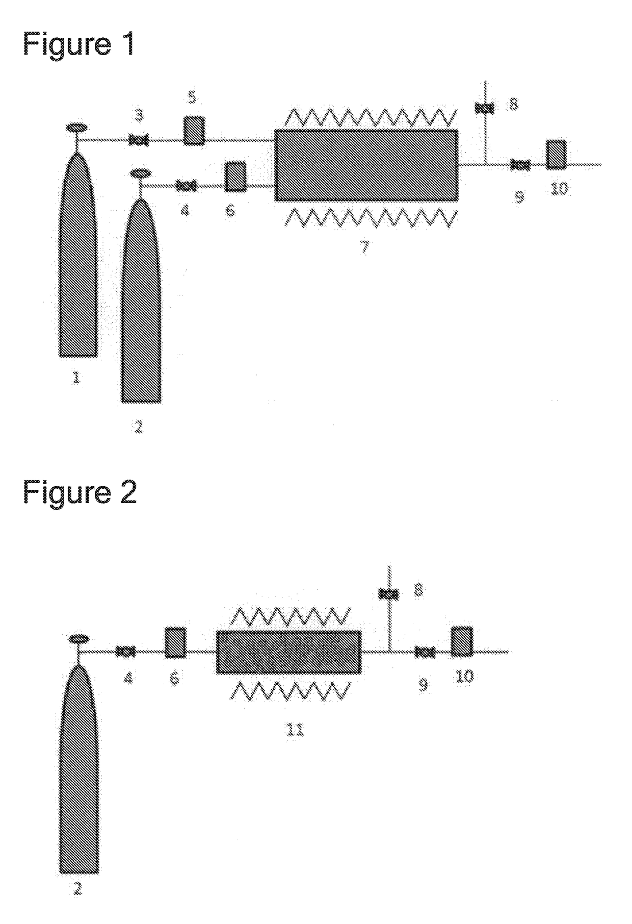
[0096]The feed time was measured of chlorine fluoride that was made to flow at 900 sccm using a chlorine fluoride feeding device shown in FIG. 1. As 1 (a gas container of material gas that contains fluorine atoms) of FIG. 1 was used a SUS 40 L gas cylinder filled with 40 kg of ClF3. As 2 (a gas container of material gas that contains chlorine atoms) was used a manganese steel 47 L gas cylinder filled with 50 kg of Cl2. As 3, 4, and 9 (pressure control device), regulators were used. As 5, 6 and 10 (flow rate control device), mass flow controllers were used. As 7 (reactor) was used a reactor provided with a SUS316L cylindrical heater having a diameter of 2 inches and a length of 1 m, that can be heated up to 400° C. As 8 (pressure control device) was used a regulator that can control pressure by computer control.

[0097]When ClF3 was loaded at 303 sccm and Cl2 at 303 sccm to the reactor (7) heated to 330° C., chlorine fluoride was fed downstream of 7 at a flow rate of 900 sccm. The flow...

example 2

[0098]The feed time was measured of chlorine fluoride that was made to flow at 900 sccm using a chlorine fluoride feeding device shown in FIG. 2. As 2 (a gas container of material gas that contains chlorine atoms) of FIG. 2 was used a manganese steel 47 L gas cylinder filled with 50 kg of Cl2. As 4 and 9 (pressure control device), regulators were used. As 6 and 10 (flow rate control device), mass flow controllers were used. As 11 (reactor) was used a reactor provided with a SUS316L cylindrical heater having a diameter of 6 inches and a length of 1 m, that can be heated up to 400° C. To this reactor was loaded 40 kg (345 mol) of CoF3. As 8 (pressure control device) was used a regulator that can control pressure by computer control.

[0099]When Cl2 was loaded at 455 sccm to the reactor (11) heated to 300° C., chlorine fluoride was fed at a flow rate of 900 sccm. The feed was stopped before CoF3 loaded into the reactor (11) was completely consumed. The time that the feed of chlorine fluo...

example 3

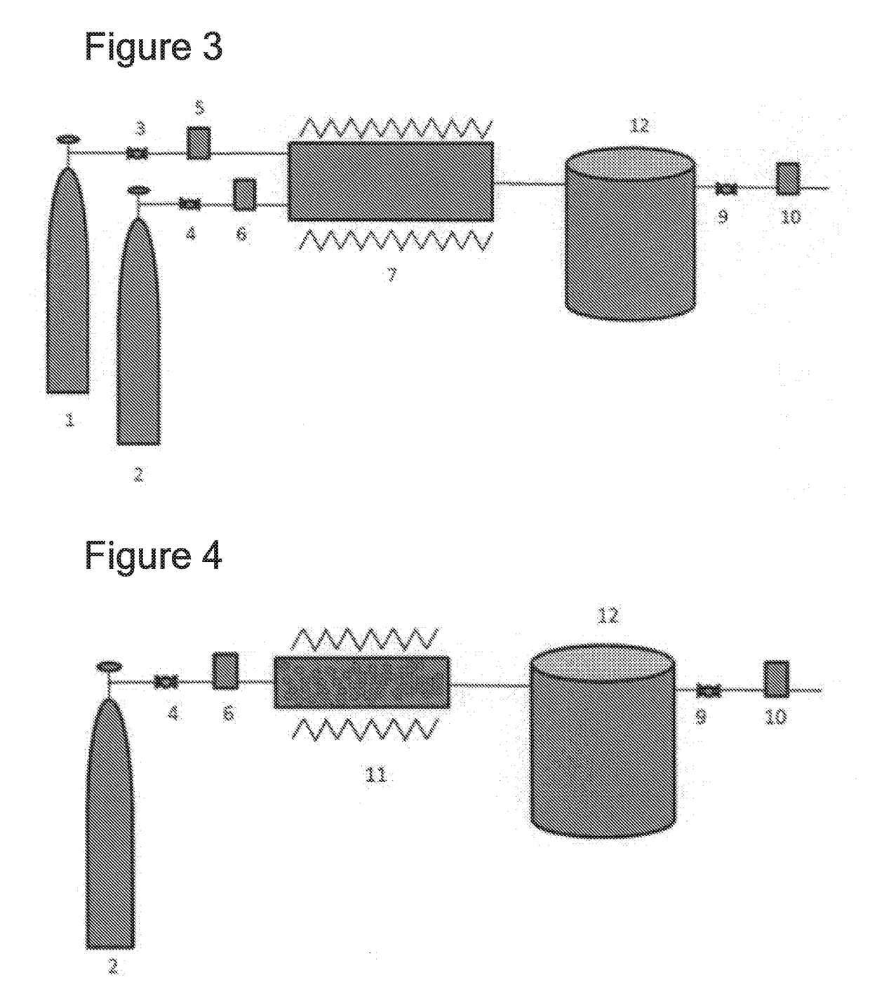
[0100]As 1 (a gas container of material gas that contains fluorine atoms) of FIG. 3 was used a manganese steel 47 L gas cylinder filled with 1.44 kg of F2. As 2 (a gas container of material gas that contains chlorine gas) was used a manganese steel 47 L gas cylinder filled with 50 kg of Cl2. As 3, 4 and 9 (pressure control device), regulators were used. As 5, 6 and 10 (flow rate control device), mass flow controllers were used. As 7 (reactor) was used a reactor provided with a SUS316L cylindrical heater having a diameter of 2 inches and a length of 1 m, that can be heated up to 400° C. The generated chlorine fluoride was liquefied by cooling to −100° C. or lower by using a SUS316L pressure container having a cooling mechanism and a temperature adjustment mechanism shown by 12 of FIG. 3. As 3, 4 and 9 (pressure control device), regulators were used. As 5, 6 and 10 (flow rate control device), mass flow controllers were used.

[0101]To the reactor (7) heated to 300° C. was loaded F2 at 2...


PUM

PropertyMeasurementUnit
boiling pointaaaaaaaaaa
pressureaaaaaaaaaa
boiling pointaaaaaaaaaa

Abstract

A chlorine fluoride feeding device and feeding process are provided that can stably generate industrially applicable chlorine fluoride (ClF), control flow rate, and provide continual feed.
The feeding process of chlorine fluoride of this invention is a feeding process to feed chlorine fluoride generated by loading a gas that contains fluorine atoms and a gas that contains chlorine atoms to a flow-type heat reactor or a plasma reactor, and it can stably generate and safely feed chlorine fluoride for a long time by reacting chlorine fluoride that is difficult to pack at a high pressure, such that an amount that can be packed in a gas container such as a gas cylinder is limited, with two or more types of gas materials that can be packed safely in a gas container by liquefaction, or with such gas material and a solid material.

Description

TECHNICAL FIELD[0001]The present invention relates to a feeding process of chlorine fluoride, and usages of the chlorine fluoride that was fed. It relates to a process for feeding chlorine fluoride stably and safely, over a long time, chlorine fluoride being a highly corrosive gas that is difficult to be packed in a gas container, such as a gas cylinder, at high pressure.BACKGROUND ART[0002]Chlorine fluoride may be used for cleaning a semiconductor manufacturing device or etching a semiconductor manufacturing device during its manufacture. In addition to semiconductors, chlorine fluoride may be used for manufacturing a MEMS device, a liquid crystal device, or solar cell device. Additionally, it may be used for manufacturing organic fluorides or inorganic fluorides.[0003]However, chlorine fluoride is highly corrosive / toxic, and a compressed gas, so it is difficult to be packed at high pressure in containers for transporting gas, such as a gas cylinder, and be circulated. This is beca...

Claims


Application Information

Patent Timeline
Patent Type & Authority Applications(United States)
IPC IPC(8): C01B7/24H01L21/306
CPCC01B7/24H01L21/30604B08B5/00B08B9/093C07B39/00H01L21/3065H01L21/02046H01L21/67017H01L21/67098H01L21/67253H01L2924/01009H01L2924/01017
Inventor TAKAHASHI, YOSHINAOKATO, KOREHITOSAKURAI, YOSHIMASATAKIZAWA, HIROKIKLKUCHI, SHOKAWAGUCHI, SHINICHIKETANI, YOSHIHIKOSHIBUSAWA, YUKINOBU
Owner KANTO DENKA IND CO LTD
Why Eureka
Try Eureka