
System and method for operating a pumped storage power plant with a double fed induction machine

a technology of induction machine and pumped storage power, which is applied in the direction of control system, electrical apparatus, and spherical frequency motor control, etc., can solve the problems of significant cyclic heat load of components, reduced service life of converters, and significant junction temperature fluctuations, so as to minimize efficiency and economic efficiency loss

Active Publication Date: 2019-02-21
GE ENERGY POWER CONVERSION TECH
View PDF0 Cites 8 Cited by
  • Summary
  • Abstract
  • Description
  • Claims
  • Application Information

AI Technical Summary

Benefits of technology

The present invention proposes measures to improve the operation of pumped storage power plants that use double fed induction machines. The invention provides a method and system for controlling the power plant in a way that maximizes control power while minimizing efficiency and economic efficiency losses. This helps to optimize the performance of the power plant.

Problems solved by technology

A disadvantage of double fed induction machines is that the cyclic heat load of the components increases significantly in an operation with increasing proximity to their synchronous speed.
In particular, semiconductor devices that are used in the power electronics of the converter, are prone to considerable junction temperature fluctuations, resulting from the operation of the machine close to the synchronous speed, by which the service life of the converter could be reduced.
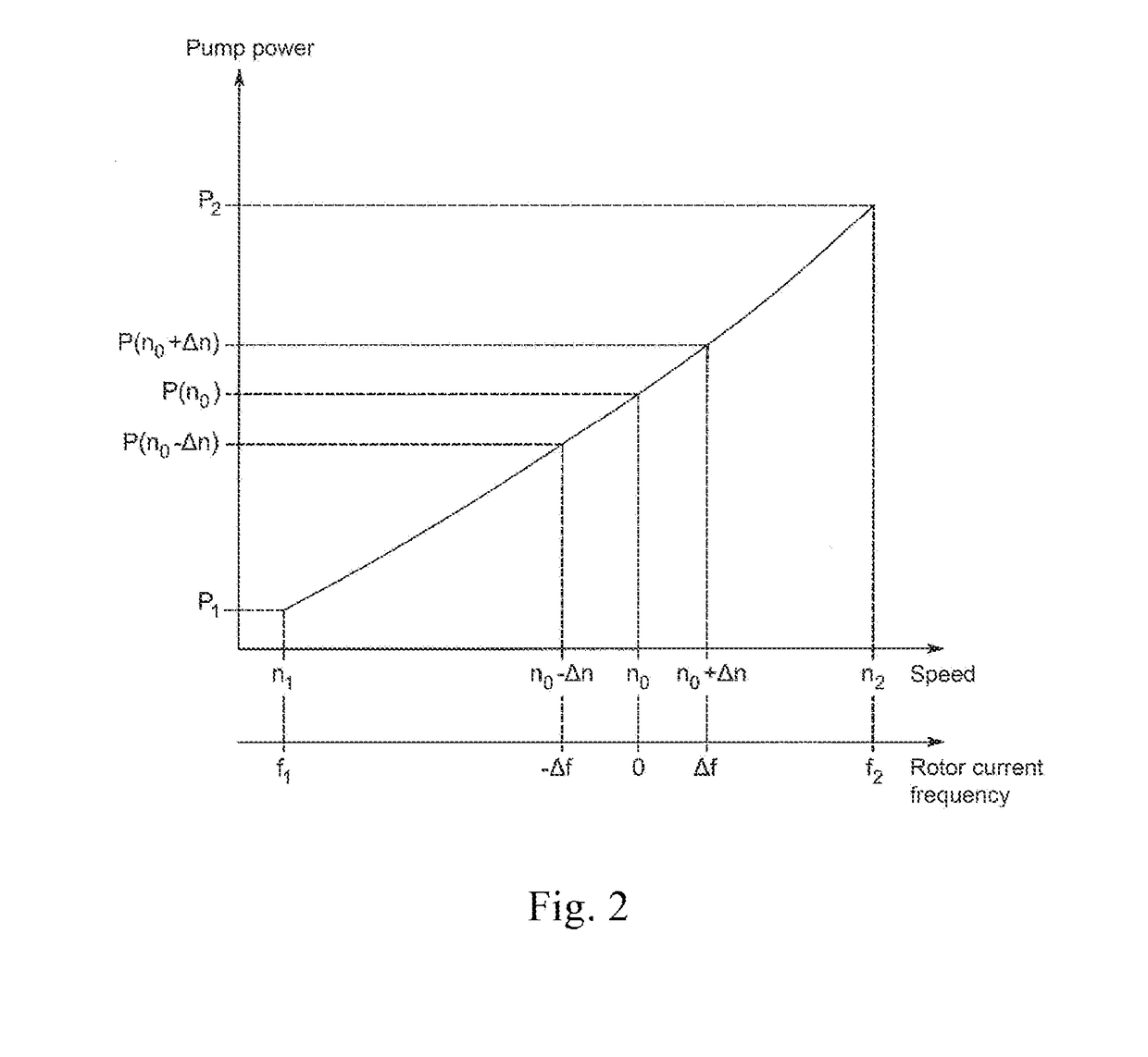
Since the frequency of the rotor current in a double fed induction machine is determined by the stator flux frequency, thus the grid frequency, and the rotor speed and an operation close to the synchronous speed results in a low rotor current frequency, these rotor currents cause considerable heat load on the semiconductor devices.
It is also known that close to the synchronous speed, the power losses are unevenly distributed on the half bridges of the converter.
Both strategies can lead to considerable efficiency and economic losses for operators of pumped storage power plants.
A wide range in which the energy of the electrical grid cannot or not optimally be used, may be unacceptable for operators of pumped storage power plants.
This results in lower power loss or a higher efficiency and economic efficiency of the pumped storage power plant.
These invariable variables also affect the thermal load of the power semiconductor switches and other components of the system and thus affect the current state of the pumped storage power plant.
Further, it is generally known that different modulation methods for the control of the power semiconductor switches of the converter, including different pulse-width modulation (PWM) types, in different operating modes of a double fed induction machine result in different power losses of the semiconductor elements of the converter and allow different permissible output currents.
When the state of the system is changed by one or more of the aforementioned remedial measures, this may have minor disadvantages, or cause impairments which include increased harmonics of voltages and currents connected to the rotor, higher current ripple, a lower reactive power available and increased auxiliary losses due to the water cooling or the use of an air cooling system.

Method used


Image

  • System and method for operating a pumped storage power plant with a double fed induction machine
  • System and method for operating a pumped storage power plant with a double fed induction machine
  • System and method for operating a pumped storage power plant with a double fed induction machine

Examples


Embodiment Construction

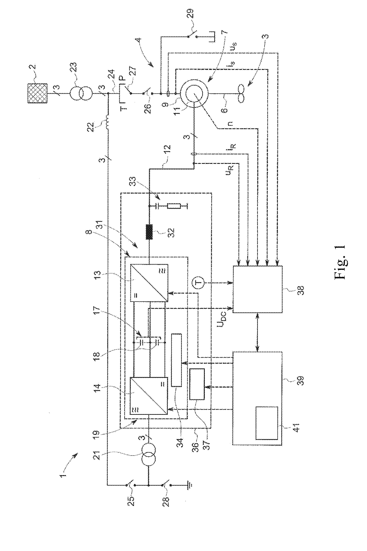
[0038]In FIG. 1 is a highly simplified block diagram representation of a pumped storage power plant 1 for storing electrical energy from an electrical grid 2 in the form of potential energy of a pumped water not shown here and the refeeding of electrical energy as required, which is obtained from the potential energy of the pumped water, into the electrical grid 2. For this purpose, the pumped storage power plant 1 is provided with a pumping / turbine device 3, which is drivingly connected to a double fed induction machine 4. Although only one single pumping / turbine device is symbolically illustrated, as it is connected with the induction machine 4 via a drive shaft 6, a plurality of pumping / turbine devices can be coupled to it via a common drive shaft 6. In addition, both integrated pump turbines and separate pumps and turbines can be used, each of which is specially optimized for pumping or turbine operation.

[0039]The double fed induction machine 4 includes essentially a motor gener...


PUM


Abstract

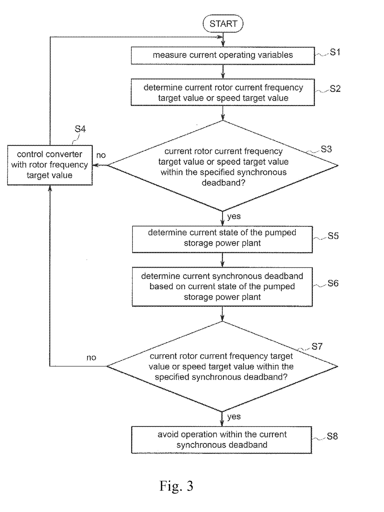
A system and method of operating a pumped storage power plant using a double fed induction machine with a frequency converter in a rotor circuit is disclosed. A current target value for the rotor current frequency is determined based on a target power to be transmitted between an electrical grid and the double fed induction machine depending on measured actual operating variables. A current inadmissible synchronous deadband is determined depending on variables characterizing a current state of the pumped storage power plant. The synchronous deadband is determined by a permissible minimum required rotor current frequency or speed difference of the rotor speed from the synchronous speed for the stationary operation. The converter is controlled to generate voltages and currents with the current target value of the rotor current frequency if the current target value of the rotor current frequency or speed does not fall in the current inadmissible synchronous deadband.

Description

FIELD OF INVENTION[0001]The present invention relates to a system and method for operating a pumped storage power plant with a double fed induction machine.BACKGROUND OF THE INVENTION[0002]In view of expanding networks for the generation and distribution of electrical energy with increasing number of power plants of different types and increased use of renewable energies, methods for storing electrical energy are becoming increasingly important. Pumped storage power plants are considered to be one of the most important, reliable and effective storage systems for electrical energy. In a pumped storage power plant, for example, an upper water reservoir is filled with the use of electrical energy with pumps, whereby the pumping current used is obtained in times of low grid load at relatively low prices. In times of high power demand, the potential energy of the water can then be used by means of a turbine in mechanical rotational energy to drive a generator to generate electrical energ...

Claims


Application Information

Patent Timeline
IPC IPC(8): H02P9/30H02P9/00H02P9/10F03B13/06
CPCH02P9/305H02P9/007H02P9/102F03B13/06H02P2101/10H02P23/08H02P2103/10H02P29/68Y02E10/20Y02E60/16
Inventor ROTHENHAGEN, KAI ALEXANDERSADOWSKI, PIOTR
Owner GE ENERGY POWER CONVERSION TECH
Learn More