Multi-functional end effector

a multi-functional, end-effector technology, applied in the direction of manufacturing tools, transportation and packaging, other manufacturing equipment/tools, etc., can solve the problems of inability to further assembly of the upper siding with the frame, inability to use conventional bolts and nuts, and excessively varied processing performance, so as to achieve high precision and efficiency.

Active Publication Date: 2019-02-28
ZHEJIANG UNIV
View PDF2 Cites 13 Cited by
  • Summary
  • Abstract
  • Description
  • Claims
  • Application Information

AI Technical Summary

Benefits of technology

[0050]6) It can be used in combination with CNC machine to realize auto drilling of high precision and efficiency.

Problems solved by technology

As one side of frame is connected with a lower siding, it is impossible to use conventional bolts and nuts to connect upper siding to be further assembled with the frame.
The CFRP and titanium alloy belongs to materials that are typically difficult for processing with excessively varied processing performance.
With regard to laminated structure formed by the two materials, fabrication of through hole with conventional drilling and milling approaches may result in ablation and lamination to the CFRP and curving to titanium alloy.
To improve hole quality, there is no choice but to repeatedly use drilling-reaming-boring technique that has such disadvantages as low efficiency, high impact from artificial factors and instable perforation quality.
This will bring forth high difficulty to processing, which may result in low processing efficiency and high processing cost.

Method used


Image

  • Multi-functional end effector
  • Multi-functional end effector
  • Multi-functional end effector

Examples


Embodiment Construction

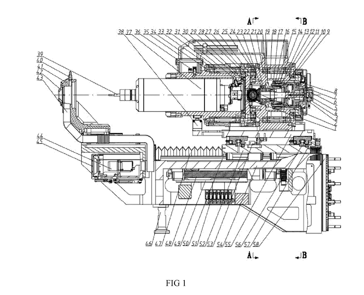
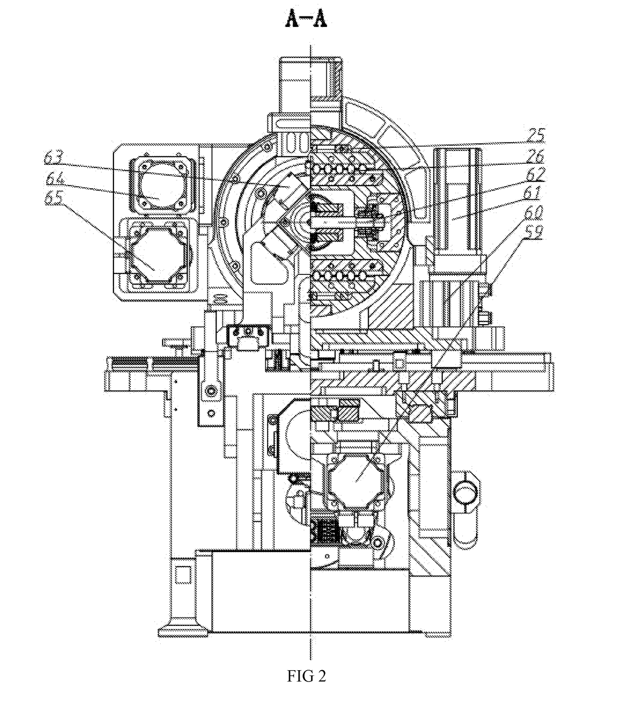
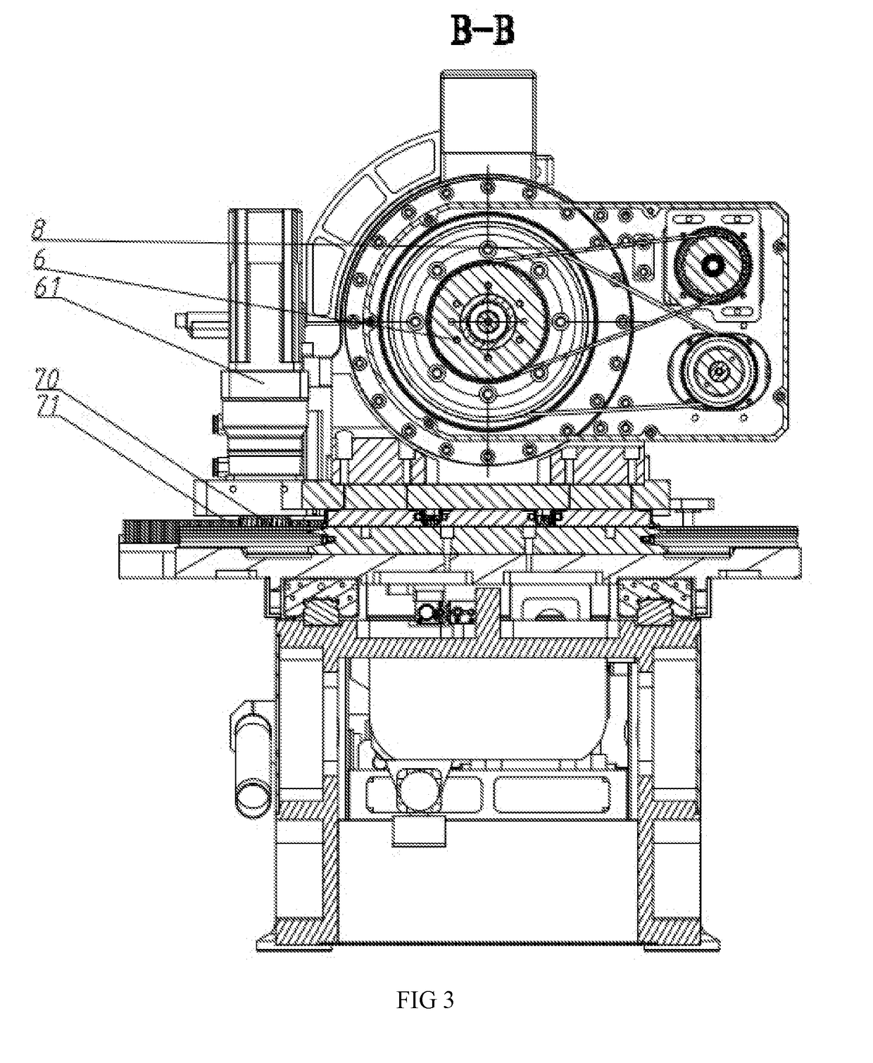
[0059]The multifunctional end effector as shown in FIGS. 1-6, comprising a bevel gear A 1, a bevel gear B 2, a revolving joint 3, a bevel gear shaft 4, a cylinder 5, a large pulley A 6, an auxiliary bearing 7, a large pulley B 8, a bearing gland A 9, a cylinder piston 10, a bearing gland B 11, a mounting base 12, a taper piston 13, a spring hollow shaft 14, a spring 15, a mounting flange 16, a spring sleeve 17, a bearing spacer A 18, a bearing seat 19, a revolving rotation shaft 20, a revolving bearing 21, a bevel gear shaft bearing 22, a bearing gland 23, an eccentric shaft auxiliary guide 24, a guide wedge 25, a cross guide pair 26, an eccentric slide 27, a bearing gland 28, a rotary seal plate 29, a spindle sleeve 30, a gas-liquid joint A 31, a bearing seat 32, a bearing spacer B 33, a stop bearing 34, a cable tray 35, a gas-liquid joint B 36, an electric spindle 37, a stop device 38, a cutting tool 39, an oil mist joint 40, a presser foot 41, a pressing sleeve 42, a chip removin...


PUM


Abstract

The present invention discloses a multifunctional end effector, comprising a base (54) and a cutting tool (39); a feed slide (52) on the base (54) and a feed driving mechanism used to drive feed slide (52) to feed cutting tool (39); a swing slide (55) on the feed slide (52) and a swing driving mechanism used to drive swing slide (55) to realize circular arc swing of cutting tool (39); a mounting base (12) on the swing slider (55); a revolving rotation shaft (20) and a rotation shaft driving mechanism used to drive revolving rotation shaft (20) to make the cutting tool rotate in the mounting base (12); an eccentric slide (27) fixed to the end of revolving rotation shaft (20); cutting tool (39) is connected to the end of eccentric slide (27) via the electric spindle (37) and an eccentric regulating mechanism used to regulate eccentric slide (27) and control radial bias of cutting tool (39). Use feed driving mechanism to realize feed of cutting tool or feed of cutting tool along the swing trail through combination with swing driving mechanism; use eccentric regulating mechanism to realize radial bias of cutting tool; make use of rotation shaft driving mechanism to realize feed of cutting tool along the helical trail; it can realize such functions as drilling, boring, reaming, helical milling and reaming of elliptical recess.

Description

FIELD OF THE INVENTION[0001]The present invention is related to the field of auto drilling for digital assembly of airplane, in particular to a multifunctional end effector.BACKGROUND ARTS[0002]Accompanied by accelerated development of aviation industry, higher requirements have been increasingly put forward for the flight performance of airplane. To reduce deadweight, and improve invisibility performance of the airplane, such materials as aluminum, titanium alloy and carbon fiber reinforced polymer (CFRP) have been applied to the wings of airplane in large quantity. Upper and lower sidings of the wings of modern airplane are in an integral structure, which has extremely higher requirements for assembly. Lower siding is to be connected to internal frame with bolts and nuts in advance in case of assembly of wings of the airplane. As one side of frame is connected with a lower siding, it is impossible to use conventional bolts and nuts to connect upper siding to be further assembled w...

Claims


Application Information

Patent Timeline
Patent Type & Authority Applications(United States)
IPC IPC(8): B23C1/025B23P23/02
CPCB23C1/025B23P23/02B23P2700/01B64F5/10B23C3/02B23C2220/28B23C2220/52B23C2265/16B23Q2210/006B23Q3/002B64F5/00
Inventor KE, YINGLINFEI, SHAOHUAJIANG, JUNXIALI, JIANGXIONGKE, ZHENZHENGDONG, HUIYUE
Owner ZHEJIANG UNIV
Why Eureka
Try Eureka