
Geological storage system of carbon dioxide and process for geological storage of carbon dioxide

a geological storage system and carbon dioxide technology, applied in the field of geological storage system of carbon dioxide and a method for geological storage of carbon dioxide, can solve the problems of not being economical, not being easy to control the behavior of carbon dioxide, and the scale of the system may become too large, so as to reduce the interfacial tension, increase the contact angle, and reduce the capillary pressure

Active Publication Date: 2019-02-28
KOREA ADVANCED INST OF SCI & TECH
View PDF0 Cites 1 Cited by
  • Summary
  • Abstract
  • Description
  • Claims
  • Application Information

AI Technical Summary

Benefits of technology

The patent describes a system and method for storing carbon dioxide in a way that reduces the pressure between the carbon dioxide and saltwater, increases the efficiency of carbon dioxide removal from a storage reservoir, and increases the amount of carbon dioxide that can be stored. These improvements make the geological storage of carbon dioxide a more viable option for reducing this emissions gas.

Problems solved by technology

However, when the carbon dioxide is stored in the saline aquifer, it may not be easy to control the behavior of carbon dioxide due to a capillary phenomenon occurring in pores disposed in the saline aquifer.
In order to increase the storage of carbon dioxide by controlling the behavior of carbon dioxide, an acid gas may be injected to change interface properties of the carbon dioxide and brine, but such a method may not be economical and may cause environmental problems.
In addition, although there is a method of pouring brine of the saline aquifer into the saline aquifer as a gas-liquid mixed fluid by saturating the carbon dioxide into micro-bubbles, water pumps or other pumps may be needed to pump up brine, the scale of the system may become too large, and energy consumption for storage may become excessive.

Method used


Image

  • Geological storage system of carbon dioxide and process for geological storage of carbon dioxide
  • Geological storage system of carbon dioxide and process for geological storage of carbon dioxide
  • Geological storage system of carbon dioxide and process for geological storage of carbon dioxide

Examples


Embodiment Construction

[0032]In the following detailed description, only certain exemplary embodiments of the present invention have been shown and described, simply by way of illustration. As those skilled in the art would realize, the described embodiments may be modified in various different ways, all without departing from the spirit or scope of the present invention. Accordingly, the drawings and description are to be regarded as illustrative in nature and not restrictive. Like reference numerals designate like elements throughout the specification. In addition, in case of well-known technologies, a detailed description thereof will be omitted.

[0033]In the drawings, the thickness of layers, films, panels, regions, etc., are exaggerated for clarity. It will be understood that when an element such as a layer, film, region, or substrate is referred to as being “on” another element, it can be directly on the other element or intervening elements may also be present. Meanwhile, when an element is referred...


PUM

PropertyMeasurementUnit
depthaaaaaaaaaa
pressureaaaaaaaaaa
pressureaaaaaaaaaa

Abstract

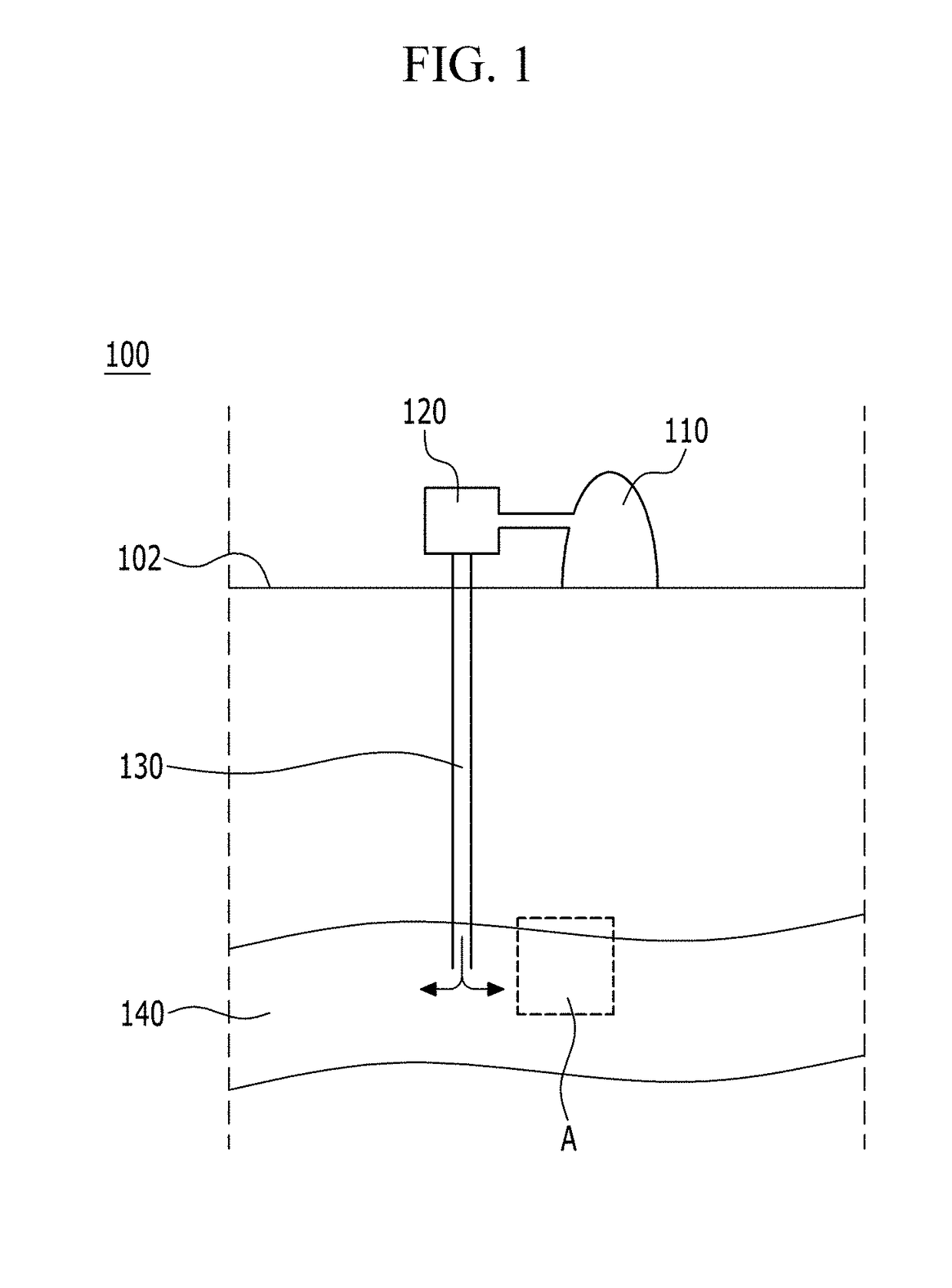
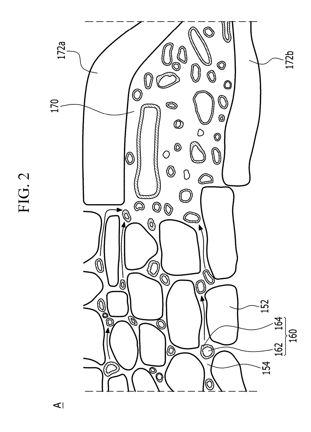
A geological storage system of carbon dioxide according to an exemplary embodiment of the present invention includes: an injection pipe that extends to a carbon storage reservoir that includes a plurality of rock grains and brine, from the ground surface, and supplies an injection material that includes carbon dioxide (CO2) to the carbon storage reservoir; a plurality of pores that are disposed between the plurality of rock grains; and a storage structure that is connected with a part of the plurality of pores and where the carbon dioxide reaches through the plurality of pores and then stored.

Description

CROSS-REFERENCE TO RELATED APPLICATION[0001]This application claims priority to and the benefit of Korean Patent Application No. 10-2017-0107819 filed in the Korean Intellectual Property Office on Aug. 25, 2017, the entire contents of which are incorporated herein by reference.BACKGROUND OF THE INVENTION(a) Field of the Invention[0002]The present invention relates to a geological storage system of carbon dioxide and a method for geologically storing carbon dioxide.(b) Description of the Related Art[0003]As a method for massively reducing greenhouse gasses to alleviate global warming, interest and demand for a carbon dioxide capture and storage (CCS) method have increased.[0004]A technology for trapping and storing carbon dioxide refers to a technology for long-term storing and managing of carbon dioxide trapped from large-scale sources of carbon dioxide such as power plants and steel mills to correspond to demand for greenhouse gas reduction because of climate change and under the K...

Claims


Application Information

Patent Timeline
Patent Type & Authority Applications(United States)
IPC IPC(8): B65G5/00C07K7/06
CPCB65G5/005C07K7/06Y02C20/40F17C1/007F17C2221/013F17C2270/0157E21B41/0064
Inventor KWON, TAE-HYUKPARK, TAEHYUNG
Owner KOREA ADVANCED INST OF SCI & TECH
Learn More