
Fuel injection device of engine

a fuel injection device and engine technology, applied in the direction of engines without rotary main shafts, machines/engines, electric control, etc., can solve the problems of increasing combustion noise, increasing combustion temperature, and unsuitable combustion, so as to improve combustion stability, stable si combustion, and stably performed

Active Publication Date: 2019-02-28
MAZDA MOTOR CORP
View PDF0 Cites 10 Cited by
  • Summary
  • Abstract
  • Description
  • Claims
  • Application Information

AI Technical Summary

Benefits of technology

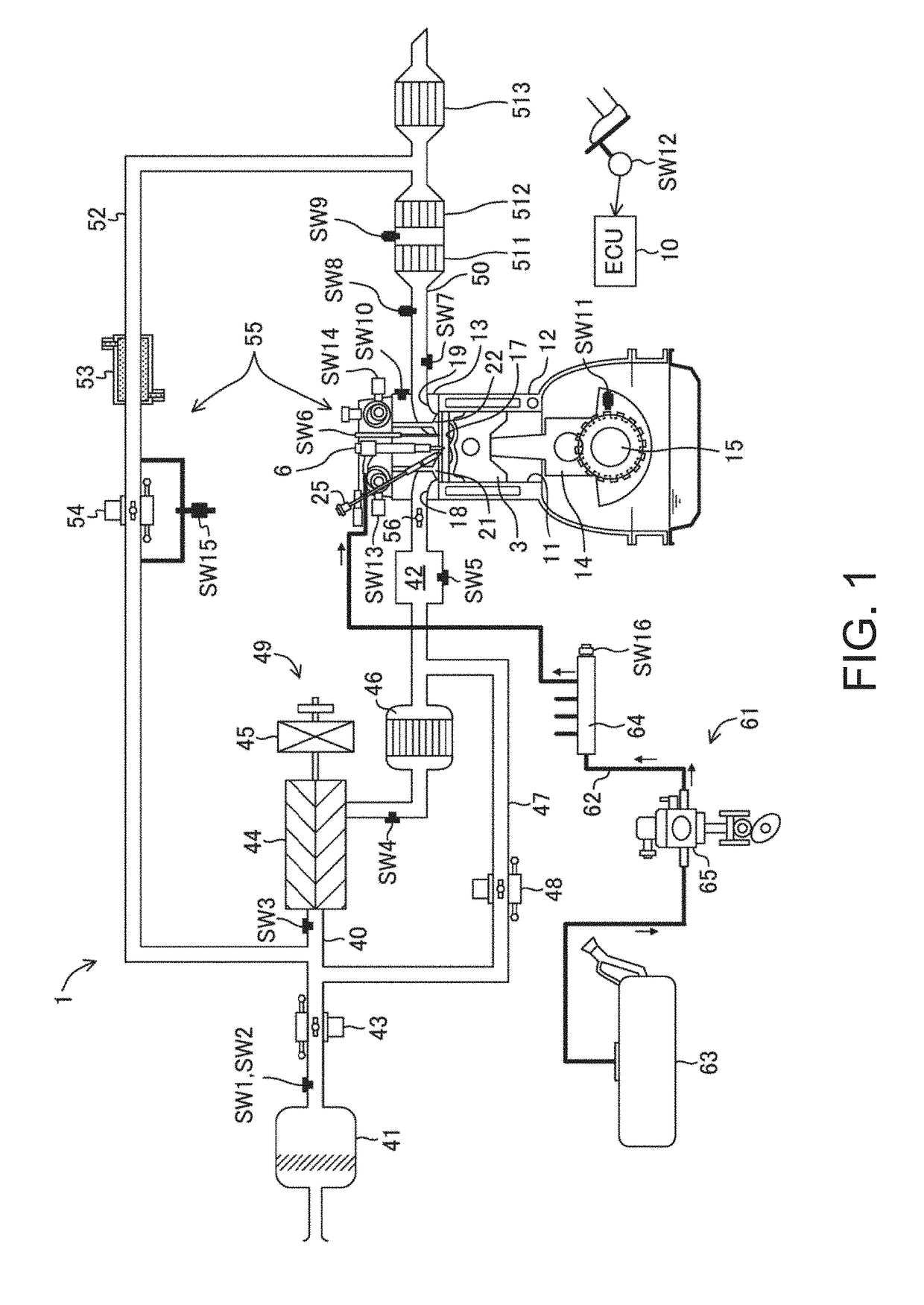
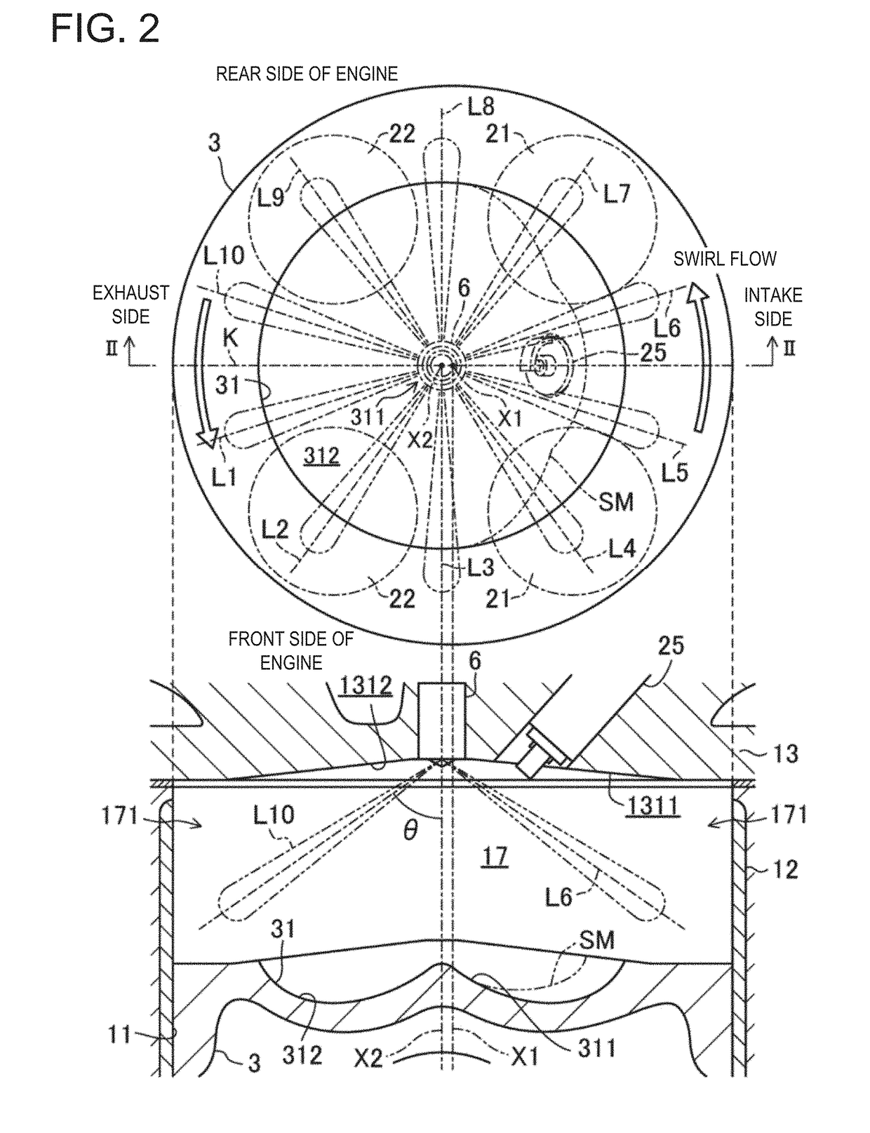
This patent is about a combustion chamber design for an engine that improves ignition stability and allows for stable self-ignition combustion. A swirl flow is generated in the combustion chamber and multiple fuel portions are injected into it. This results in a more stable ignition and combustion process, regardless of changes in the volume of the combustion chamber or the engine's operating state. Overall, this design ensures a stable and high-quality combustion in the engine.

Problems solved by technology

For example, if sections with different fuel concentrations (thick and thin sections) scatter around and an uneven mixture gas is formed, suitable combustion cannot be performed.
This increases combustion noise, excessively raises a combustion temperature, and generates NOR, and ignition becomes unstable and stable combustion becomes difficult.

Method used


Image

  • Fuel injection device of engine
  • Fuel injection device of engine
  • Fuel injection device of engine

Examples


Embodiment Construction

[0050]Hereinafter, embodiments of the present disclosure are described in detail with reference to the accompanying drawings. Note that the following description is essentially nothing more than an illustration, and is not to limit the present disclosure, an application thereof, or a usage thereof.

[0051]The present inventors considered a combustion mode in which SI (Spark Ignition) combustion and CI (Compression Ignition) combustion are combined. The SI combustion is combustion accompanying flame propagation which starts by forcibly igniting mixture gas inside a combustion chamber. The CI combustion is combustion which starts by the mixture gas inside the combustion chamber self-igniting by being compressed. In the combustion mode combining the SI combustion and the CI combustion, the mixture gas inside the combustion chamber is forcibly ignited to start its combustion through flame propagation, and heat generated by the SI combustion and pressure increase thereby cause combustion o...


PUM


Abstract

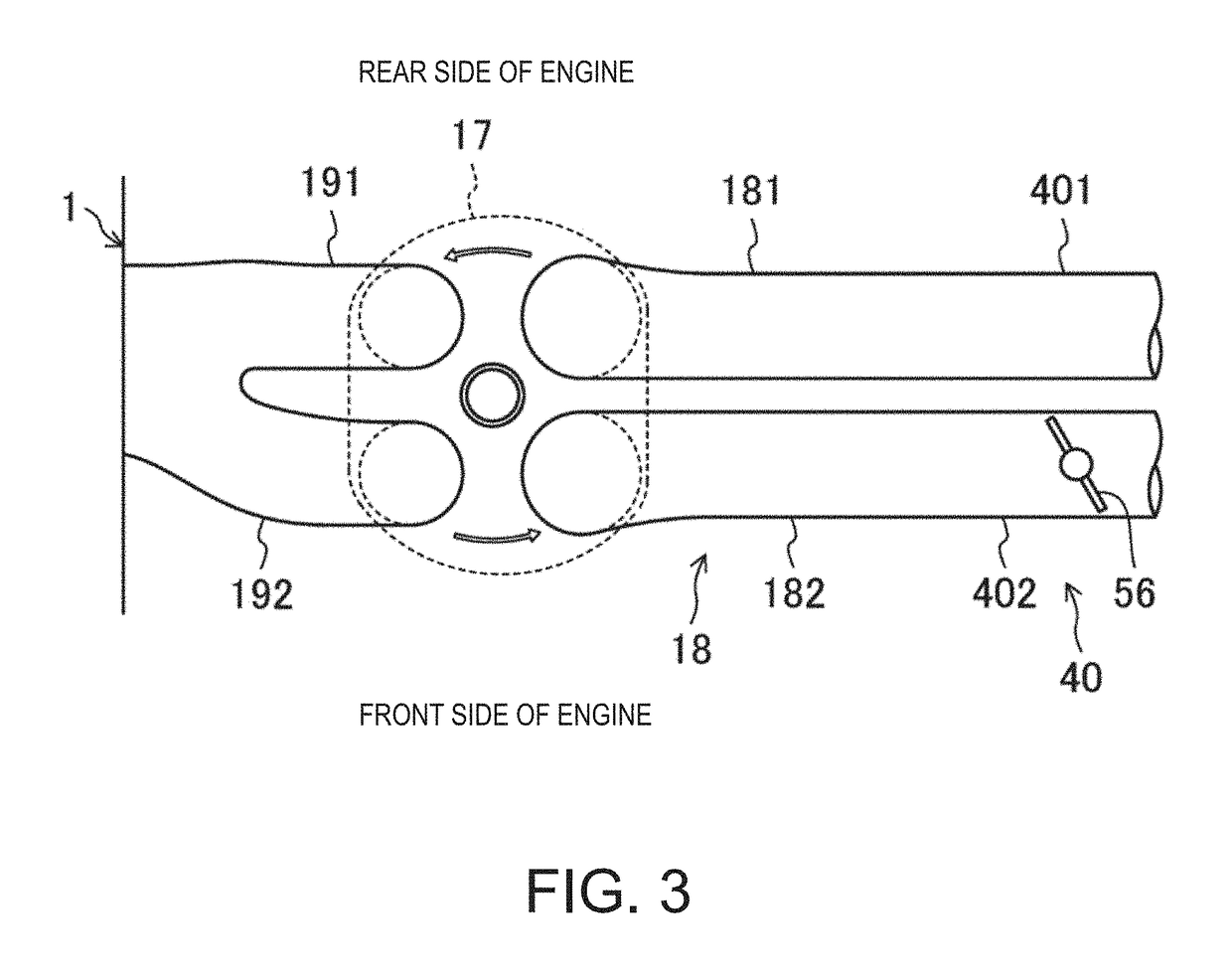
A control device of an engine including a cylinder, a piston, a cylinder head, and a combustion chamber is provided, which includes intake and exhaust ports, a swirl control valve provided in an intake passage connected to the intake port, a fuel injection valve attached to the cylinder head to be oriented into the center of the combustion chamber in a plan view thereof, and having first and second nozzle ports, and a control unit. The control unit includes a processor configured to execute a swirl opening controlling module to output the control signal to the swirl control valve to have a given opening at which a swirl ratio inside the combustion chamber becomes 2 or above, and a fuel injection timing controlling module to output the control signal to the fuel injector to inject fuel at a given timing at which the swirl ratio becomes 2 or above.

Description

TECHNICAL FIELD[0001]The present disclosure relates to a fuel injection device of an engine.BACKGROUND OF THE DISCLOSURE[0002]JP2009-108778A discloses a fuel injection device which causes fuel to whirl and diffuse in a swirl flow to form a stratified mixture gas. Specifically, an auxiliary injection in which a small amount of fuel is injected is performed in a final stage of compression stroke. By causing the fuel to whirl and diffuse in the swirl flow, the stratified mixture gas is formed around a spark plug, and the stratified mixture gas is ignited to cause a fire. During or after combustion of this mixture gas, a main injection of fuel is performed. Thus, compression ignition surely occurs.[0003]However, with the configuration described in JP2009-108778A, a suitable distribution of a mixture gas is not formed within a combustion chamber.[0004]Therefore, the present disclosure aims to provide a fuel injection device of an engine, which forms a suitable mixture gas distribution wi...

Claims


Application Information

Patent Timeline
Patent Type & Authority Applications(United States)
IPC IPC(8): F02D19/02F02M61/14F02D19/06F02D41/00F02D41/30F02M21/02
CPCF02D19/024F02M61/14F02D19/0642F02D19/0689F02D19/0694F02D41/0062F02D41/3047F02M21/0278F02M21/0275F02M67/14F02M61/1893F02M2200/46F02M2200/44F02D43/00F02D41/3023F02D41/3041F02D41/401F02D41/402F01B11/00F02B2023/106F02B2023/108F02D2041/0015Y02T10/40Y02T10/30F02M61/1806
Inventor MATSUMOTO, KOTAURUSHIHARA, TOMONORISUEOKA, MASANARIMARUYAMA, KEIJIMIYAMOTO, TORUKOSHIRO, YUDAIPAK, GYETAE
Owner MAZDA MOTOR CORP
Learn More