Battery state estimating device

a state estimation and battery technology, applied in secondary battery servicing/maintenance, instruments, cad techniques, etc., can solve the problems of deteriorating accuracy of battery parameters identification, reduce risk, avoid the effect of reducing the identification accuracy of resistance parameters

Active Publication Date: 2019-02-28
DENSO CORP
View PDF1 Cites 14 Cited by
  • Summary
  • Abstract
  • Description
  • Claims
  • Application Information

AI Technical Summary

Benefits of technology

[0007]The main object of the present disclosure is to provide a battery state estimating device capable of avoiding decrease in the estimation accuracy of the state of the secondary battery when the temperature of the secondary battery is low and also avoiding decrease in the identification accuracy of the battery parameters constituting the battery model.
[0012]When the temperature of the secondary battery is low, the nonlinear characteristic of current-voltage due to the charge transfer resistance becomes dominant. Thus, in the above disclosure, the charge transfer resistance model is configured to be a model derived from the Butler-Volmer equation of electrochemistry and expressing the nonlinear characteristics of the secondary battery. Specifically, this model includes a charge parameter which is a parameter corresponding to an exchange current density of the Butler-Volmer equation and is correlated with the temperature of the secondary battery. Since the charge parameter depends on the temperature of the secondary battery, it is possible to accurately represent the current-voltage nonlinear characteristics at low temperature using the charge parameter, which could not be expressed by the technique described in the above-mentioned PTL 1.
[0013]In the above disclosure, in addition to the information on the resistance parameter and the time constant parameter of the diffusion resistance model, information on the charge parameter is stored in the storage unit in advance in association with temperature information of the secondary battery. The parameter calculating unit calculates each of the resistance parameter, the time constant parameter, and the charge parameter that correspond to the detected temperature value based on a detected temperature value of the secondary battery and the information stored in the storage unit. The state estimating unit estimates the state of the secondary battery based on the calculated resistance parameter, time constant parameter, and charge parameter. According to the above disclosure which uses the charge parameter, it is possible to prevent the estimation accuracy of the state of the secondary battery from decreasing when the temperature of the secondary battery is low.
[0016]Therefore, the identifying unit of the above disclosure sequentially identifies the resistance parameter and the time constant parameter with the Kalman filter using, as initial values, a resistance parameter and a time constant parameter calculated based on the information stored in the storage unit in advance. This makes it possible to appropriately set the initial values used with the Kalman filter, and thus reduces the risk that the appropriate solution cannot be found, such as the solution converging to a local solution. As a result, it is possible to avoid decrease in the identification accuracy of the resistance parameter and the time constant parameter, and thus to avoid decrease in the estimation accuracy of the state of the secondary battery.

Problems solved by technology

Further, according to the device described in PTL 1, when appropriate initial values are not set for the battery parameters, which are to be identified by the Kalman filter, for example, the solution may converge to a local solution which deviates greatly from the optimum solution, and thus there is a risk that the accuracy of the identification of the battery parameters deteriorates.

Method used


Image

  • Battery state estimating device
  • Battery state estimating device
  • Battery state estimating device

Examples


first embodiment

[0047]A first embodiment of a battery state estimating device according to the present disclosure will be described below with reference to the drawings. In the present embodiment, the battery state estimating device is applied to a vehicle.

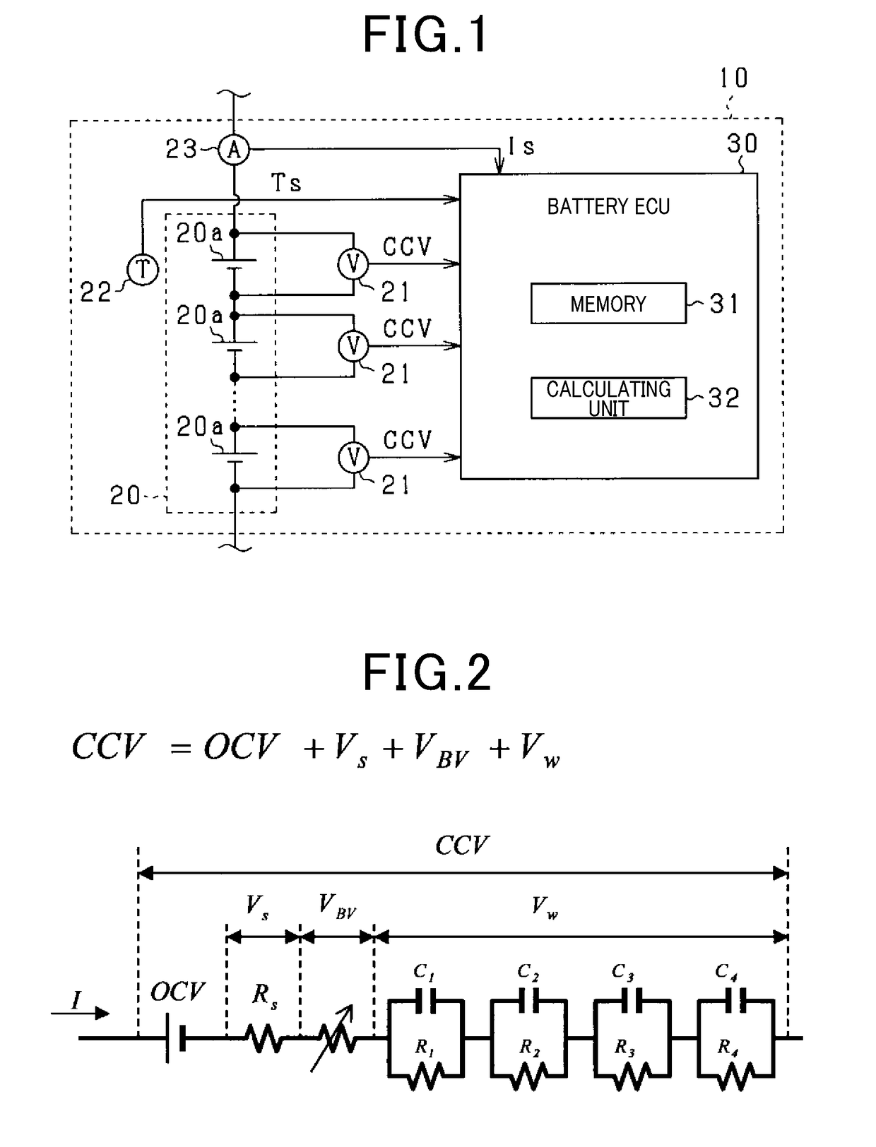
[0048]As shown in FIG. 1, a battery pack 10 is mounted on a vehicle and includes a battery pack 20 and a battery ECU 30. The battery pack 20 is composed of a series connection of a plurality of battery cells 20a. In the present embodiment, the vehicle is assumed to be a vehicle equipped with a rotating electrical machine as its main engine, specifically, for example, a hybrid vehicle or an electric vehicle. The battery pack 20 exchanges electric power with the rotating electric machine or the like. The battery cells 20a are secondary batteries, and in the present embodiment, lithium ion secondary batteries are used. Note that the vehicle is not limited to a vehicle having a rotating electric machine as its main engine, but may be a vehicle that u...

second embodiment

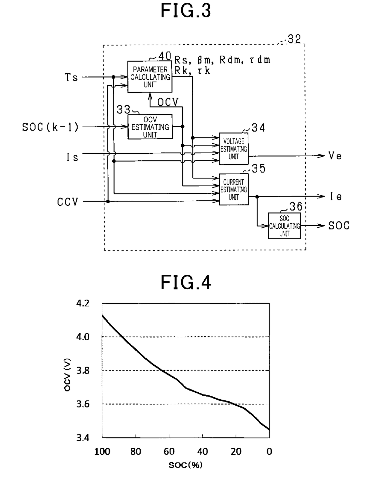
[0134]The second embodiment will now be explained with reference to the drawings, focusing on its differences from the first embodiment. In the present embodiment, the calculation method of the SOC calculating unit 36 is changed. In the present embodiment, the detected current Is is inputted to the SOC calculating unit 36 shown in FIG. 3.

[0135]FIG. 23 is a block diagram of the SOC calculating unit 36 according to the present embodiment.

[0136]A deviation calculating unit 36a subtracts the detected current Is from the estimated current Ie calculated by the current estimating unit 35 and outputs the result. A gain multiplying unit 36b multiplies the output value of the deviation calculating unit 36a by the gain B. An adding unit 36c adds the detected current Is to the output value of the gain multiplying unit 36b. A calculating unit 36d calculates the SOC of the battery cell 20a based on the output value Ig of the adding unit 36c. In the present embodiment, the SOC is calculated by cha...

third embodiment

[0150]A third embodiment will now be explained with reference to the drawings, focusing on its differences from the first embodiment. In the present embodiment, in addition to the resistance parameter Rdm and the time constant parameter τdm, the charge parameter βm is sequentially identified and updated by the UKF. This is performed in view of the fact that the charge parameter may deviate from the appropriate value due to deterioration of the battery cell 20a or the like.

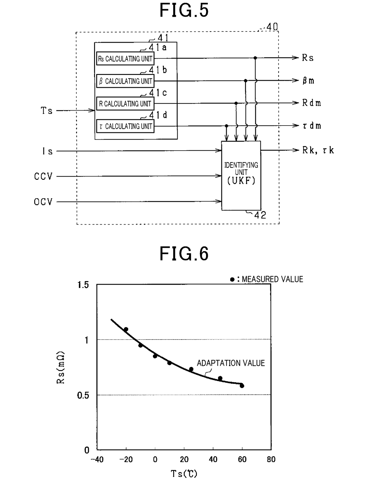
[0151]As shown in FIG. 26, the identifying unit 42 composing the parameter calculating unit 40 sequentially identifies a third correction coefficient βk as a charge correction coefficient for correcting the charge parameter βm. The third correction coefficient βk identified by the identifying unit 42 is sequentially stored in the memory 31. In FIG. 26, for the sake of convenience, the components that are shown in FIG. 5 are denoted by the same reference numbers.

[0152]The third correction coefficient βk is a paramet...


PUM


Abstract

A battery model includes a series connection of a direct current resistance model, a charge transfer resistance model derived from the Butler-Volmer equation, and a diffusion resistance model. A battery state estimating device includes a storage unit and a parameter calculating unit. The storage unit stores information on the resistance parameter related to the resistance component of the diffusion resistance model, the time constant parameter related to the time constant of the diffusion resistance model, and the charge parameter of the charge transfer resistance model, in association with temperature information of the secondary battery. The parameter calculating unit calculates each of the parameters corresponding to the detected temperature value based on a detected temperature value of the secondary battery and the information stored in the storage unit. The parameter calculating unit sequentially identifies parameters used for estimating the state using the Kalman filter and the calculated parameters as initial values.

Description

CROSS REFERENCE TO RELATED APPLICATION[0001]The present application is based on Japanese Application No. 2016-017527 filed on Feb. 1, 2016, the contents of which are incorporated herein by reference.TECHNICAL FIELD[0002]The present disclosure relates to a battery state estimating device configured to estimate the state of a secondary battery based on a battery model of the secondary battery.BACKGROUND ART[0003]One known device of this kind, as disclosed in PTL 1, has a battery model of a secondary battery comprising a DC resistor and a series connection of a plurality of RC parallel circuits and sequentially identifies battery parameters which are the resistance component and capacitance component constituting the RC parallel circuits by the Unscented Kalman Filter (UKF).CITATION LISTPatent Literature[0004][PTL 1] JP 2014-74682 ASUMMARY OF THE INVENTION[0005]The battery model described in PTL 1 is not configured such that the characteristics of the current-voltage nonlinear region o...

Claims


Application Information

Patent Timeline
Patent Type & Authority Applications(United States)
IPC IPC(8): G01R31/36G06F17/50
CPCG01R31/367G01R31/389G06F17/5009G06F2217/16G01R31/392H01M10/48H01M10/425G06F2119/06G06F30/367Y02E60/10G06F30/20G06F2111/10
Inventor KAWAI, TOSHIYUKIKATO, KEIICHIKOIKE, YUJITANAKA, HIDEAKIKONO, SHUNTARO
Owner DENSO CORP
Why Eureka
Try Eureka