Compressor arrangement supplying charged air to a combustion engine

a compressor arrangement and combustion engine technology, applied in the direction of machines/engines, mechanical equipment, liquid fuel engines, etc., can solve the problems of affecting the normal air flow in the air intake passage, disturbing the recirculation flow, and affecting the air flow to the compressor, etc., to achieve the optimal operating properties of the compressor, reduce the air flow rate to the combustion engine, and large the effect of the operating area

Inactive Publication Date: 2019-03-07
SCANIA CV AB
View PDF3 Cites 2 Cited by
  • Summary
  • Abstract
  • Description
  • Claims
  • Application Information

AI Technical Summary

Benefits of technology

[0013]According to an embodiment of the invention, the housing comprises a hollow portion configured to receive a shaft connecting the compressor wheel and a turbine wheel. In this case, the compressor is a part of a turbo charger. The compressor wheel is driven by the turbine wheel and the exhaust gases of the combustion engine. The problem with surge may arise in a compressors of a turbo charger when the air flow rate to the combustion engine is drastically reduced at the same time as the turbine is still spinning with a high speed generating power to the compressor wheel. In diesel engines, this problem will arise when the fuel supply to the engine ends. Since the exhaust manifold has a smaller volume of exhaust gases than the volume of charged air in the charged air line, parts of the accumulated charge air risks to leak through the compressor in a backward direction. However, the abov...

Problems solved by technology

Inevitably, recirculating of air in an air intake passage disturbs the ordinary air flow in the air intake passage.
In this case, the recirculated flow will disturb the air flow ...

Method used


Image

  • Compressor arrangement supplying charged air to a combustion engine
  • Compressor arrangement supplying charged air to a combustion engine
  • Compressor arrangement supplying charged air to a combustion engine

Examples


Embodiment Construction

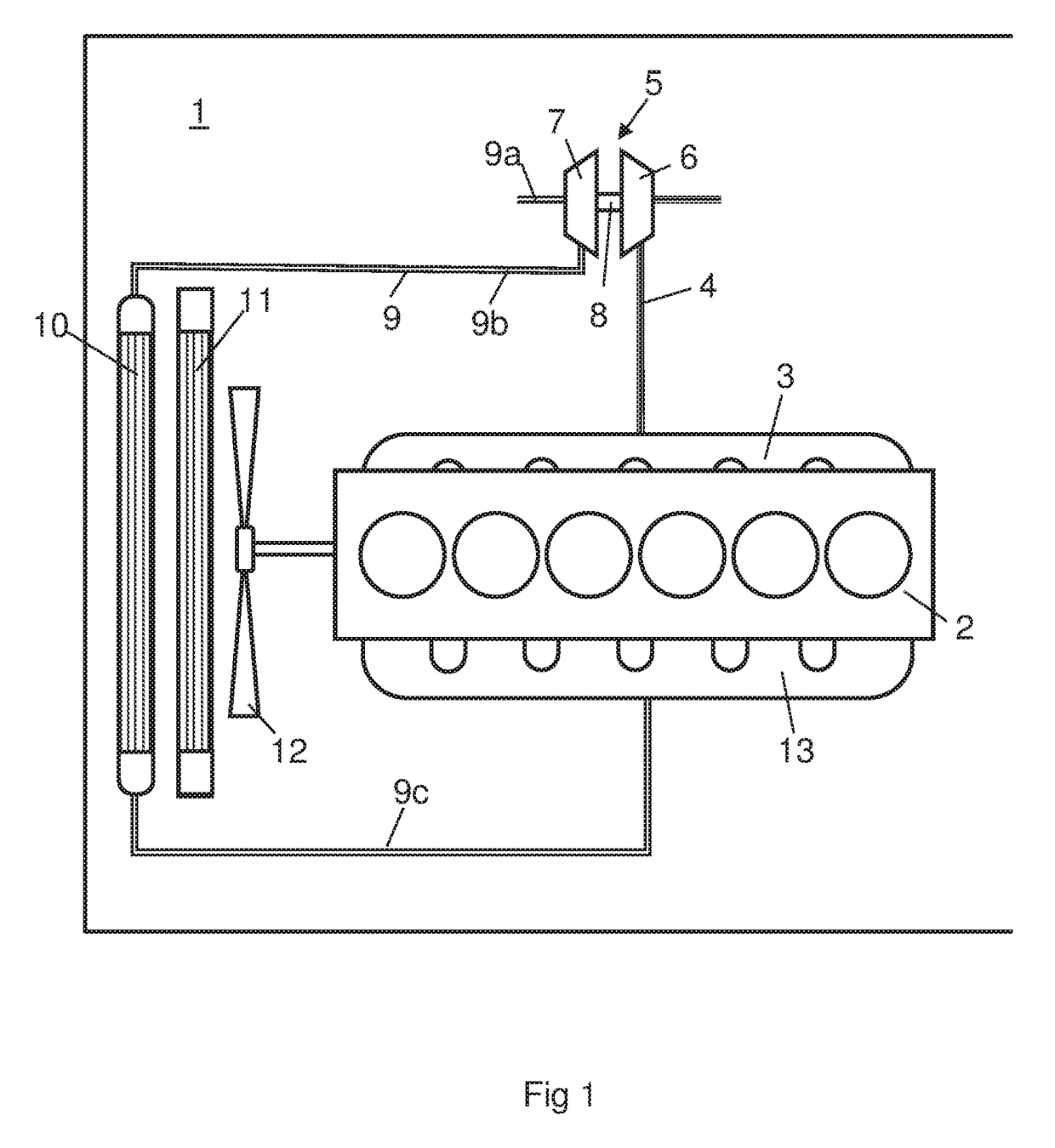
[0019]FIG. 1 shows a compressor for a combustion engine 2 powering a schematically indicated vehicle 1. The vehicle 1 may be a heavy vehicle and the combustion engine 2 may be an internal combustion engine such as a diesel engine. The exhaust gases from the cylinders of the combustion engine 2 are led via an exhaust manifold 3 to an exhaust line 4. The combustion engine 2 is provided with a turbo charger 5 comprising a turbine wheel 6 and a compressor wheel 7. The exhaust gases are initially led, via the exhaust line 4, to the turbine wheel 6. The pressure of the exhaust gases provide a driving power of the turbine wheel 6 which is transmitted, via a shaft 8, to the compressor wheel 7. As a consequence, the exhaust gases leaving the turbine wheel 6 have a reduced pressure. The compressor wheel 7 is arranged in a charge air line 9 directing charge air to the combustion engine 2. During operation of the compressor wheel 7, air is drawn from the surrounding, via a first air line 9a of ...


PUM


Abstract

Provided is a compressor arrangement in an air line supplying charged air to a combustion engine. The compressor arrangement comprises a compressor unit comprising a housing including an air intake passage, a compressor wheel arranged in said air intake passage, and an additional air passage allowing recirculation of air from the air intake passage in a position radially outwardly of a part of the compressor wheel. The additional air passage is configured to allow recirculation of air to an air conduit delivering an air flow to the air intake passage of the compressor unit.

Description

CROSS-REFERENCE TO RELATED APPLICATION(S)[0001]This application is a national stage application (filed under 35 § U.S.C. 371) of PCT / SE2017 / 050093, filed Feb. 3, 2017 of the same title, which, in turn claims priority to Swedish Application No. 1650359-1, filed Mar. 17, 2016 of the same title; the contents of each of which are hereby incorporated by reference.FIELD OF THE INVENTION[0002]The present invention relates to a compressor arrangement supplying charge air to a combustion engine.BACKGROUND OF THE INVENTION[0003]A compressor of a turbo charger increases the power of a combustion engine by supplying charge to the combustion engine. The operation of a compressor can be defined in a compressor map plotting mass flow as a function of pressure ratio. The boundary of a stable operating region in such a map is defined by a surge limit. Operation of the compressor in a region outside the stable operating region may result in what is known as surge. Surge is defined by an irregular and...

Claims


Application Information

Patent Timeline
IPC IPC(8): F02B37/16F02B39/16F04D27/02F04D29/42F04D29/68
CPCF02B37/16F02B39/16F04D27/0238F04D29/4213F04D29/685F05D2220/40F02B2037/125F02B37/12Y02T10/12F02C6/12F02M35/10F04D27/0207
Inventor HALLDORF, ERIKNILSSON, PER-ERIKTELBORN, KLAS
Owner SCANIA CV AB
Why Eureka
Try Eureka