Depth measurement using multiple pulsed structured light projectors

a structured light and projector technology, applied in the field of depth measurement, can solve the problems of poor performance of existing depth measurement systems under high ambient lighting conditions, and the inability to achieve the effect of conventional depth measurement systems under high ambient lighting conditions, and achieve the effect of increasing the signal-to-noise ratio

Inactive Publication Date: 2019-03-07
META PLATFORMS TECH LLC
View PDF4 Cites 19 Cited by
  • Summary
  • Abstract
  • Description
  • Claims
  • Application Information

AI Technical Summary

Benefits of technology

[0003]A depth measurement assembly (DMA) projects pulses of structured light into a local area (e.g., an area surrounding a HMD). The DMA captures image data of the local area that include the structured light that has been scattered / reflected by objects in the local area, and uses the captured image data to determine depth information for the objects in the local area. In some embodiments, one or more of the pulses are high-peak-power pulses that can overwhelm strong ambient light. Thus, the high-peak-power pulses can increase the signal-to-noise ratio in conditions with strong ambient light.

Problems solved by technology

But, existing depth measurement systems have a drawback of poor performance under high ambient lighting conditions, because the active illumination system has to generate a signal that is strong enough for depth measurement system to distinguish it ambient background light.
Accordingly, effectiveness of conventional depth measurement systems is impaired under high ambient lighting, such as outdoor under bright solar illumination.

Method used


Image

  • Depth measurement using multiple pulsed structured light projectors
  • Depth measurement using multiple pulsed structured light projectors
  • Depth measurement using multiple pulsed structured light projectors

Examples


Embodiment Construction

System Overview

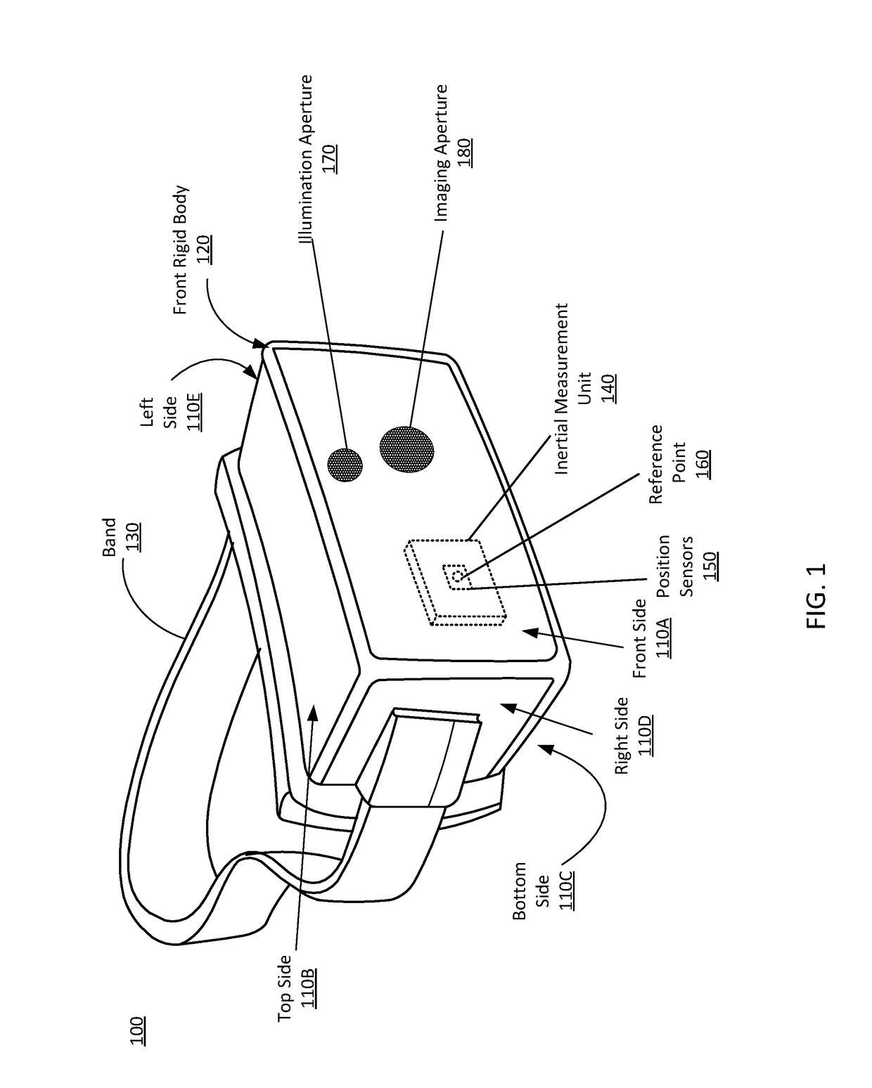
[0016]FIG. 1 is a wire diagram of a HMD 100, in accordance with an embodiment. The HMD 100 may be part of, e.g., a VR system, an AR system, a MR system, or some combination thereof. In embodiments that describe AR system and / or a MR system, portions of the HMD 100 that are between a front side 110A of the HMD 100 and an eye of the user are at least partially transparent (e.g., a partially transparent electronic display). The HMD 100 includes a front side 110A, a top side 110B, a bottom side 110C, a right side 110D, a left side 110E, a front rigid body 120, and a band 130. The front rigid body 120 also includes an inertial measurement unit (IMU) 140, the one or more position sensors 150, and a reference point 160. In the embodiment shown by FIG. 1, the position sensors 150 are located within the IMU 140, and neither the IMU 140 nor the position sensors 150 are visible to the user.

[0017]The IMU 140 is an electronic device that generates fast calibration data based on me...


PUM


Abstract

A depth measurement assembly (DMA) includes a pulsed illuminator assembly, a depth camera assembly, and a controller. The pulsed illuminator assembly has a structured light projector that projects pulses of structured light at a pulse rate into a local area. The depth camera assembly captures images data of an object in the local area illuminated with the pulses of structured light. An exposure interval of the depth camera assembly is pulsed and synchronized to the pulses projected by the pulsed illuminator assembly. The controller controls the pulsed illuminator assembly and the depth camera assembly so that they are synchronized. The controller also determine depth and / or tracking information of the object based on the captured image data. In some embodiments, the pulsed illuminator assembly have a plurality of structured light projectors that projects pulses of structured light at different times.

Description

BACKGROUND[0001]The present disclosure generally relates to depth measurement, and specifically relates to using a plurality of pulsed structured light projectors for depth measurement in head-mounted display (HMD) applications.[0002]Depth measurement is an important feature for HMD systems, such as systems used in virtual reality (VR) and augmented reality (AR) applications. Depth measurements systems typically include some sort of active illumination system that projects light into a local area (e.g., structured light, and light pulse, etc.). The depth measurement system then uses images of the local area that include the projected light in order to determine depth to objects in the local area. But, existing depth measurement systems have a drawback of poor performance under high ambient lighting conditions, because the active illumination system has to generate a signal that is strong enough for depth measurement system to distinguish it ambient background light. Accordingly, eff...

Claims


Application Information

Patent Timeline
Patent Type & Authority Applications(United States)
IPC IPC(8): G02B27/01G01B11/22G06T7/507H04N13/02
CPCG02B27/0176G01B11/22H04N13/25G06T7/507G06T19/006G02B2027/0127G02B2027/0138G02B27/0172G01B11/2513G01B5/0014H04N23/60
Inventor HALL, MICHAEL
Owner META PLATFORMS TECH LLC
Why Eureka
Try Eureka