Color image display device and color image display method

a display device and color image technology, applied in the field of color image display devices, can solve the problems of low light-use efficiency of liquid crystal display devices using color filters, and achieve the effects of preventing color breakage, and reducing power consumption of light source portions

Inactive Publication Date: 2019-04-11
SHARP KK
View PDF2 Cites 9 Cited by
  • Summary
  • Abstract
  • Description
  • Claims
  • Application Information

AI Technical Summary

Benefits of technology

[0033]In the first aspect of the invention, since at least two of the first to third light sources emit light sequentially during the white field period, power consumed by the light source portion generating white light is reduced. Thus, in the case of the field-sequential liquid crystal display device, color breakup is prevented by setting the white field period, and the reduced power consumption of the light source portion renders it possible to inhibit a cost increase due to a larger power supply circuit and a larger radiation mechanism.
[0034]In the second aspect of the invention, since the respective emission periods of the first to third light sources occur symmetrically in the direction of time during the predetermined period within the white field period, it is possible to suppress an increase in power consumption of the light source portion and inhibit disturbance of color balance due to a transient characteristic of the optical response of the spatial light modulation portion, thereby maintaining satisfactory color reproducibility.
[0035]In the third aspect of the inventio

Problems solved by technology

However, about ⅔ of the backlight that illuminates a liquid crystal panel is absorbed by the color filte

Method used


Image

  • Color image display device and color image display method
  • Color image display device and color image display method
  • Color image display device and color image display method

Examples


first embodiment

1. First Embodiment

[0059]

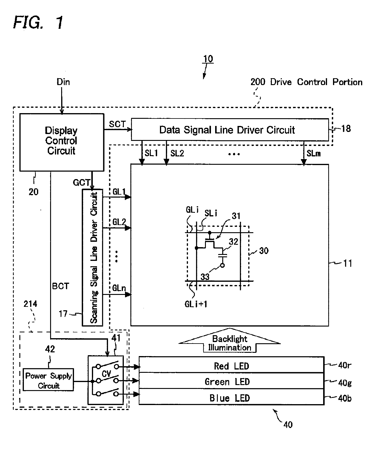
[0060]FIG. 1 is a schematic block diagram illustrating an overall configuration of a field-sequential liquid crystal display device according to a first embodiment of the present invention. The liquid crystal display device 10 displays a color image by a field-sequential system in which one frame period is divided into four field periods. The liquid crystal display device 10 includes a liquid crystal panel 11, a display control circuit 20, a scanning signal line driver circuit 17, a data signal line driver circuit 19, a backlight unit 40, and a backlight driver circuit 214 including a lighting control circuit 41 and a power supply circuit 42. Note that the display control circuit 20, the scanning signal line driver circuit 17, the data signal line driver circuit 18, and the backlight driver circuit 214 constitute a drive control portion 200. Moreover, the liquid crystal panel 11 functions as a spatial light modulation portion driven by the scanning signal li...

second embodiment

2. Second Embodiment

[0104]Next, a field-sequential liquid crystal display device according to a second embodiment of the present, invention will be described. In this embodiment, as in the first embodiment, a color image is displayed by a field-sequential system in which one frame period is divided into four field periods Tw, Tb, Tg, and Tr, and any features other than the emission pattern during the W-field period Tw are the same as in the first embodiment (see FIGS. 1 to 5). Therefore, in the present embodiment, elements that are the same as or correspond to those in the first embodiment are denoted by the same reference characters, any detailed descriptions thereof will be omitted, and the following description will mainly focus on a configuration related to the emission pattern during the W-field period Tw.

[0105]When compared to the first embodiment, the present embodiment prioritizes ensuring a proper emission luminance (white image display luminance) during the W-field period ...

third embodiment

3. Third Embodiment

[0114]Next, a field-sequential liquid crystal display device according to a third embodiment of the present invention will be described. In this embodiment, as in the first embodiment, a color image is displayed by a field-sequential system in which one frame period is divided Into four field periods Tw, Tb, Tg, and Tr, and any features other than the emission pattern during the W-field period Tw are the same as in the first embodiment (see FIGS. 1 to 5). Therefore, in the present embodiment, elements that are the same as or correspond to those in the first embodiment are denoted by the same reference characters, any detailed descriptions thereof will be omitted, and the following description will mainly focus on a configuration related to the emission pattern during the W-field period Tw.

[0115]FIG. 11 is a timing chart showing an example of the emission pattern during the W-field period Tw in the present, embodiment. In the present embodiment, the LED control cir...


PUM


Abstract

The present invention provides a field-sequential color image display device suppressing color breakup and an increase in power consumption. The liquid crystal display device displays a color image by a field-sequential system in which each frame period includes four field periods corresponding to four colors, white, blue, green, and red, and the liquid crystal display device includes a light source portion which includes blue, green, and red LEDs, and a light source driver circuit. The light source driver circuit generates blue, green, and red light source control signals CswB, CswG, and CswR, and drives the light source portion on the basis of these signals. At this time, the light source driver circuit generates the light source control signals CswB, CswG, and CswR such that the blue, green, and red LEDs emit light sequentially during an ON period Ton within a white field period Tw, and respective emission periods for the colors occur symmetrically with respect to the axis of symmetry at the midpoint of the ON period Ton in the direction of time.

Description

TECHNICAL FIELD[0001]The present invention relates to color image display devices, mote specifically to a color image display device, such as a liquid crystal display device, which displays a color image by a field-sequential system.BACKGROUND ART[0002]Most liquid crystal display devices that display color images include color filters respectively transmitting red (R), green (G), and blue (B) light therethrough, the filters being provided for each set of three subpixels into which each pixel is divided. However, about ⅔ of the backlight that illuminates a liquid crystal panel is absorbed by the color filters, and therefore such a liquid crystal display device using color filters has low light-use efficiency. Accordingly, field-sequential liquid crystal display devices, which achieve display in colors without using color filters, are drawing attention.[0003]In the case of a typical field-sequential liquid crystal display device, one frame period, which is a display period for one scr...

Claims


Application Information

Patent Timeline
IPC IPC(8): G09G3/34
CPCG09G3/3413G02B6/0068G02F1/133603G02F1/133621G02F2001/133622G02F2203/34G09G2310/0235G09G2320/0242G09G3/3426G09G3/3648G09G2330/021G09G2310/08G09G3/36G09G3/20G09G3/34G02F1/133622
Inventor ISHIHARA, TOMOYUKI
Owner SHARP KK
Why Eureka
Try Eureka