High voltage electric line cutter device

a cutting device and high-voltage technology, applied in the direction of electric devices, battery cutoff switches, manufacturing tools, etc., can solve the problems of extreme risk, occupants and emergency personnel responding, and the possibility of electrocution or the combustion of flammable materials

Active Publication Date: 2019-04-11
KEY SAFETY SYST
View PDF25 Cites 21 Cited by
  • Summary
  • Abstract
  • Description
  • Claims
  • Application Information

AI Technical Summary

Benefits of technology

[0009]The igniter is electrically activated in the event of a signal from a sensor. In a preferred embodiment, the electric line cutter device is configured to be used in a vehicle capable of generating high voltages wherein the electric line cutter device is activated by the sensor in the event of a vehicle crash. The igniter preferably is a pyrotechnic device and further comprises a propellant charge squib. The upper or lower housing further comprises one or more blow-out vent passages extending from inside the chamber externally out through one of said upper or lower housings. The electric line cutter device preferably has a filter to capture debris generated during the breaking of the busbar and in particular to cool down and deionize the plasma. The filter is made of a high temperature resistant material, preferably, steel or woven steel.

Problems solved by technology

In the event of a vehicle crash, the electrical current flowing from the batteries can become a serious hazard particularly as the current flows can be shorted to electrify a vehicle chassis with very high voltage.
This creates a hazard for the occupants as well as emergency personnel responding to the accident.
The possibility of electrocution or of the combustion of flammable material is an extreme risk.
A manual off switch is unreliable for many reasons, because the driver may be incapacitated and emergency personnel may not be able to safely access such a switch.

Method used


Image

  • High voltage electric line cutter device
  • High voltage electric line cutter device
  • High voltage electric line cutter device

Examples


Embodiment Construction

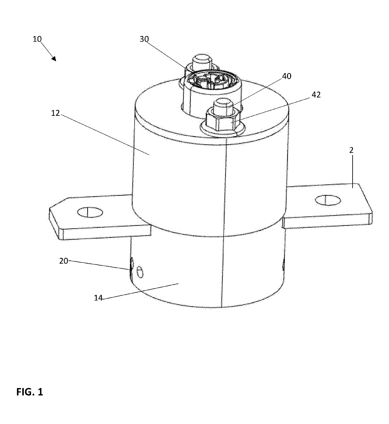
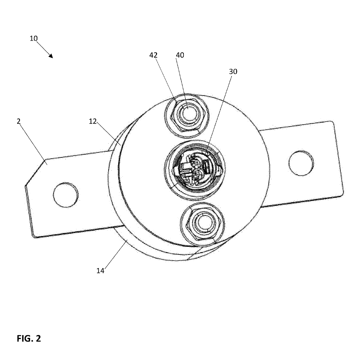
[0024]An electric line cutter device 10 for high voltage busbars 2 is illustrated in FIGS. 1-4. The device 10 has an upper housing 12 and a lower housing 14. Sandwiched between the upper 12 and lower housing 14 is a busbar 2. The busbar 2 is designed to carry high voltage currents and can be used as a means for carrying power from a battery system to the various components of a vehicle as way of example.

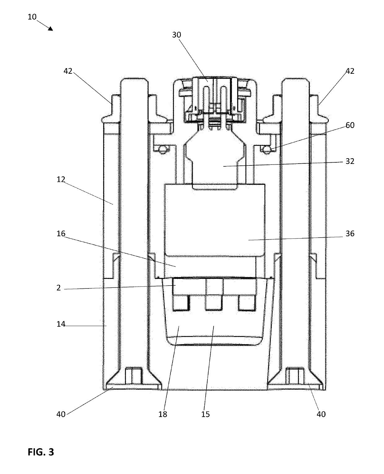
[0025]Shown at a top portion of the device 10 are electrical connections for an igniter 30. As illustrated in FIG. 1, the two housing parts 12, 14 are held together by fasteners 40 when tightened by threaded nuts 42. This is also illustrated in the cross-sectional view of FIG. 3.

[0026]With reference to FIG. 3, the fasteners 40 when engaging the nut 42 extend through the lower housing 14 and upper housing 12 and when tightened clamp tightly about the busbar 2. As shown, the igniter 30 further includes a squib 32 with propellant. This forms a pyrotechnic device that is capable to prope...


PUM

PropertyMeasurementUnit
timeaaaaaaaaaa
timeaaaaaaaaaa
currentaaaaaaaaaa

Abstract

An electric line cutter device for high voltage busbars has a two-part housing, a piston, an igniter and a busbar. The upper housing includes a cylinder, cuboid or prism chamber. The lower housing also includes a cylinder, cuboid or prism chamber. The piston is contained inside one of either the upper housing chamber or the lower housing chamber. Upon igniting the igniter, the piston breaks a portion of the busbar moving the piston and the portion of the busbar into the opposite chamber thereby stopping the electric current flow. The piston is at least partially formed as an insulator to prevent electric discharge. The piston design together with chamber design includes integrated “squeeze areas” and “blow channels” for the appearing arc. A channel system outside or from inside the piston allow the pyro gases to push the arc plasma into a filter system to cool down the gases.

Description

FIELD OF THE INVENTION[0001]The present invention relates to a device for extremely rapid termination of very high voltages and currents. More particularly, a device that upon a sensed signal can disrupt current flow in milliseconds. The device is particularly useful in vehicle crashes, more particularly, electric vehicle crashes. In general, the device also allows for protection from damages and risks by short cuts of high voltage batteries where the device can also be used for stationary batteries, not only for batteries in electric vehicles.BACKGROUND OF THE INVENTION[0002]The use of hybrid and fully electric powered vehicles means a bank of batteries carrying very high voltages is required. In the event of a vehicle crash, the electrical current flowing from the batteries can become a serious hazard particularly as the current flows can be shorted to electrify a vehicle chassis with very high voltage. This creates a hazard for the occupants as well as emergency personnel respond...

Claims


Application Information

Patent Timeline
Patent Type & Authority Applications(United States)
IPC IPC(8): H01H39/00H01H71/02H01H50/54B23D15/14B60L11/18B60L3/04H02B1/20
CPCH01H39/006H01H71/02H01H50/546B23D15/14B60L11/1851B60L3/04H02B1/20H01H2039/008B23D15/145B60L3/0007H01H9/342
Inventor VOLKMANN, MATTHIASPIERUCH, MARTINSTRUSS, HEIKOMAUTHOFER, ALOIS
Owner KEY SAFETY SYST
Why Eureka
Try Eureka