Supercharge Your Innovation With Domain-Expert AI Agents!

Fluidized bed coking with fuel gas production

a coking process and fuel technology, applied in coke ovens, combustible gas production, thermal non-catalytic cracking, etc., can solve the problems of low liquid yield of transportation fuels, degrade the quantity of more valuable liquid products, and generally poor quality of liquids, so as to reduce capital costs and improve the effect of return

Inactive Publication Date: 2019-04-18
EXXON RES & ENG CO
View PDF3 Cites 0 Cited by
  • Summary
  • Abstract
  • Description
  • Claims
  • Application Information

AI Technical Summary

Benefits of technology

The new Flexicoking unit is a modified version of a conventional three section unit that can convert heavy oil feeds to lower boiling liquid hydrocarbon products with minimal coke yield while being constructed with lower capital expenditure. The new unit eliminates the heater and uses a modified gasifier with internal or external cyclones to separate coke particles from the product gas. Both cold and hot coke are combined to supply heat for the cracking reactions and form coke in the reactor. The coke is withdrawn to remove excess coke and purge the system of metals and ash. Technical effects of this patent include improved efficiency and cost-effectiveness of heavy oil conversion and removal of excess coke from the system.

Problems solved by technology

Carbon rejection processes generally operate at moderate to high temperatures and low pressures and suffer from a lower liquid yield of transportation fuels than hydrogen addition processes, because a large fraction of the feedstock is rejected as solid coke; light gases are also formed as by-products in the thermal cracking reactions and, being of high H / C ratio tend to degrade the quantity of the more valuable liquid products.
The liquids are generally of poor quality and must normally be hydrotreated before they can be used as feeds for catalytic processes to make transportation fuels.

Method used


Image

  • Fluidized bed coking with fuel gas production
  • Fluidized bed coking with fuel gas production
  • Fluidized bed coking with fuel gas production

Examples


Embodiment Construction

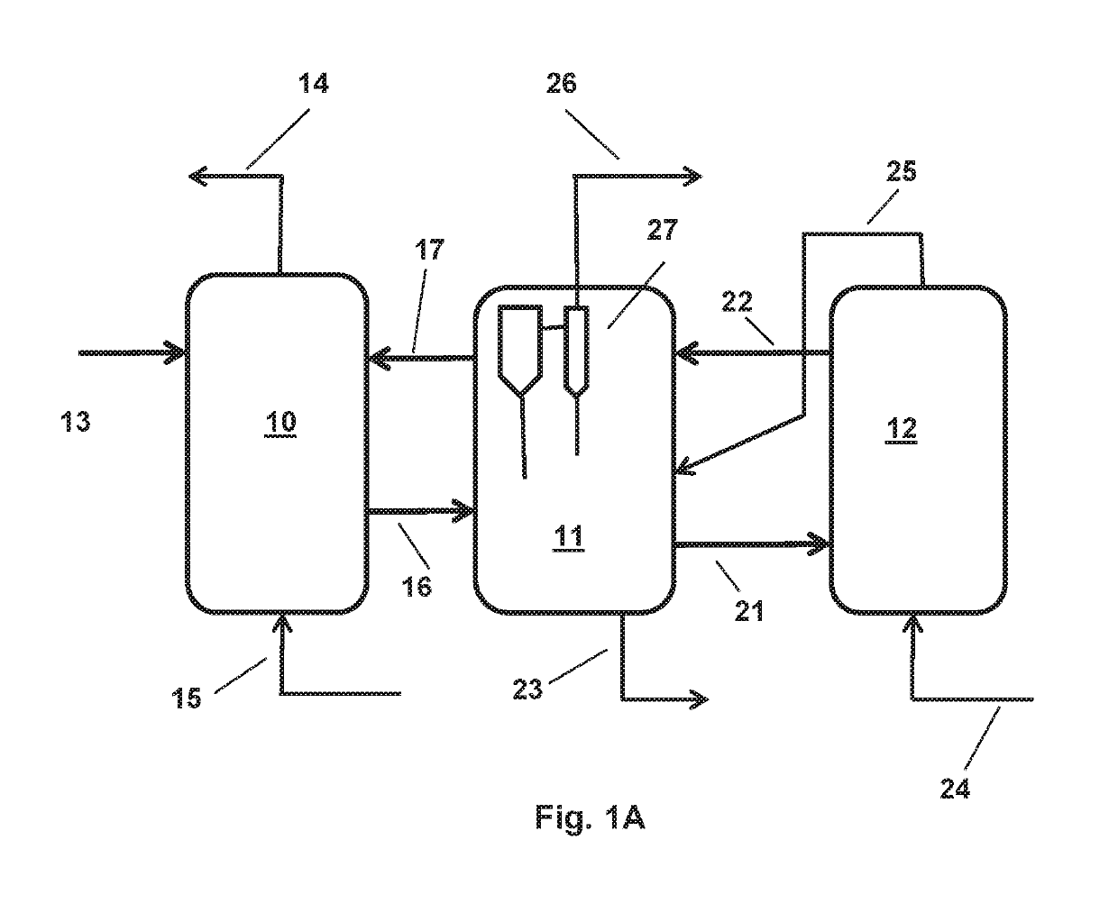
[0023]In this description, the term “Flexicoking” (trademark of ExxonMobil Research and Engineering Company) is used to designate the fluid coking process in which heavy petroleum feeds are subjected to thermal cracking in a fluidized bed of heated solid particles to produce hydrocarbons of lower molecular weight and boiling point along with coke as a by-product which is deposited on the solid particles in the fluidized bed, the coke is then converted to a fuel gas by contact at elevated temperature with steam and an oxygen-containing gas in a gasification reactor (gasifier).

[0024]FIG. 1A shows a Flexicoker unit with its characteristic three reaction vessels—reactor, heater and gasifier—in side-by-side arrangement; although the footprint of the side-by-side arrangement is larger than that of the stacked units shown in U.S. Pat. Nos. 3,661,543 and 3,816,084, it is less subject to upsets and potential equipment failures as noted in U.S. Pat. No. 3,759,676 and has now become convention...


PUM

PropertyMeasurementUnit
pressureaaaaaaaaaa
temperatureaaaaaaaaaa

Abstract

A Flexicoking™ unit which retains the capability of converting heavy oil feeds to lower boiling liquid hydrocarbon products while making a fuel gas from rejected coke to provide only a minimal coke yield. The heater section of the conventional three section unit (reactor, heater, gasifier) is eliminated and all or a portion of the cold coke from the reactor is passed directly to the gasifier which is modified by the installation of separators to remove coke particles from the product gas which is taken out of the gasifier for ultization. In one embodiment, a portion of cold coke is transferred directly from the reactor to the gasifier, and another portion of cold coke is combined with hot, partly gasified coke particles transferred directly from the gasifier to the reactor. The hot coke from the gasifier is passed directly to the coking zone of the reactor to supply heat to support the endothermic cracking reactions and supply seed nuclei for the formation of coke in the reactor. Coke is withdrawn from the gasifier to remove excess coke and to purge the system of metals and ash.

Description

CROSS-REFERENCE TO RELATED APPLICATIONS[0001]This application is a continuation-in-part of and claims priority to U.S. application Ser. No. 14 / 729,101, filed Jun. 3, 2015, and U.S. Provisional Application Ser. No. 62 / 014,762 filed Jun. 20, 2014, the contents of all of which are herein incorporated by reference in their entirety.FIELD OF THE INVENTION[0002]This invention relates to a fluid coking process in which a heavy oil feed is subjected to thermal cracking (coking) in a fluidized bed reactor with the coke product being converted by gasification to form a fuel gas.BACKGROUND OF THE INVENTION[0003]Heavy petroleum oils and residual fractions derived from them are characterized by a combination of properties which may be summarized as high initial boiling point, high molecular weight and low hydrogen content relative to lower boiling fractions such as naphtha, gasoline, and distillates; frequently these heavy oils and high boiling fractions exhibit high density (low API gravity), h...

Claims


Application Information

Patent Timeline
Patent Type & Authority Applications(United States)
IPC IPC(8): C10J3/48C10J3/66C10J3/72C10G9/32
CPCC10J3/482C10J3/66C10J3/487C10J3/723C10G9/32C10J2200/15C10J2200/39C10J2300/0943C10J2300/0956C10J2300/1603C10J2300/1807C10J3/84C10J2300/0976C10J3/463C10J3/62C10B55/10
Inventor RAJAGOPALAN, SURIYANARAYANANPHILLIPS, GLEN E.HARANDI, MOHSEN N.
Owner EXXON RES & ENG CO
Features
  • R&D
  • Intellectual Property
  • Life Sciences
  • Materials
  • Tech Scout
  • Unparalleled Data Quality
  • Higher Quality Content
  • 60% Fewer Hallucinations
Learn More