
Optical-Filter-Cell-Array Structure and Method of Manufacturing the Same

a technology of optical filter and cell array, which is applied in the direction of glass tempering apparatus, manufacturing tools, instruments, etc., can solve the problems of glass substrate breaking, difficult to handle and process glass substrate, and high cost of glass substrate, so as to improve the coating property of the optical filter layer, improve the strength, and slim the effect of the optical filter

Active Publication Date: 2019-06-13
UTI INC
View PDF0 Cites 4 Cited by
  • Summary
  • Abstract
  • Description
  • Claims
  • Application Information

AI Technical Summary

Benefits of technology

The present invention aims to solve problems in the related art by providing an optical-filter-cell-array structure where an optical filter is easy to store and supply. The method of manufacturing the structure involves utilizing a tempered glass substrate and a cell array. The technical effects include easy storage and supply of the optical filter and improved manufacturing efficiency.

Problems solved by technology

This glass substrate may be broken by external impact or stress.
In the case of a commercially available near-infrared-cut filter, the glass substrate is thick, and it is very difficult to handle and process the glass substrate if the glass substrate is thin.
However, when the resin substrate is used, there are problems in that the cost is higher than that of a glass substrate, bending due to external stress occurs, or the coating yield of the oxide multi-layered film is low.
Further, in the case of the conventional glass substrate (generally using borosilicate glass) or resin substrate, stress is generated due to the difference in thermal expansion coefficient between a deposition material and a substrate during deposition of a near-infrared-absorption layer or a reflection layer, causing warpage of the substrate.
Accordingly, it is difficult to realize deposition conditions due to the warpage of the conventional substrate.
Accordingly, there is a limit in the extent to which the thickness of the image pickup apparatus can be reduced, which limits the slimming of the smart phone.
However, the smaller the thickness of the glass substrate, the lower the strength thereof, which is considered the biggest problem.
There is another problem in that processing and handling methods thereof are not easy.
In this case, the difference in stress between the glass substrate and the oxide causes a decrease in the strength of the glass substrate, which is a more critical problem in the case of a thin glass plate of 0.3 T or less.

Method used


Image

  • Optical-Filter-Cell-Array Structure and Method of Manufacturing the Same
  • Optical-Filter-Cell-Array Structure and Method of Manufacturing the Same
  • Optical-Filter-Cell-Array Structure and Method of Manufacturing the Same

Examples


Embodiment Construction

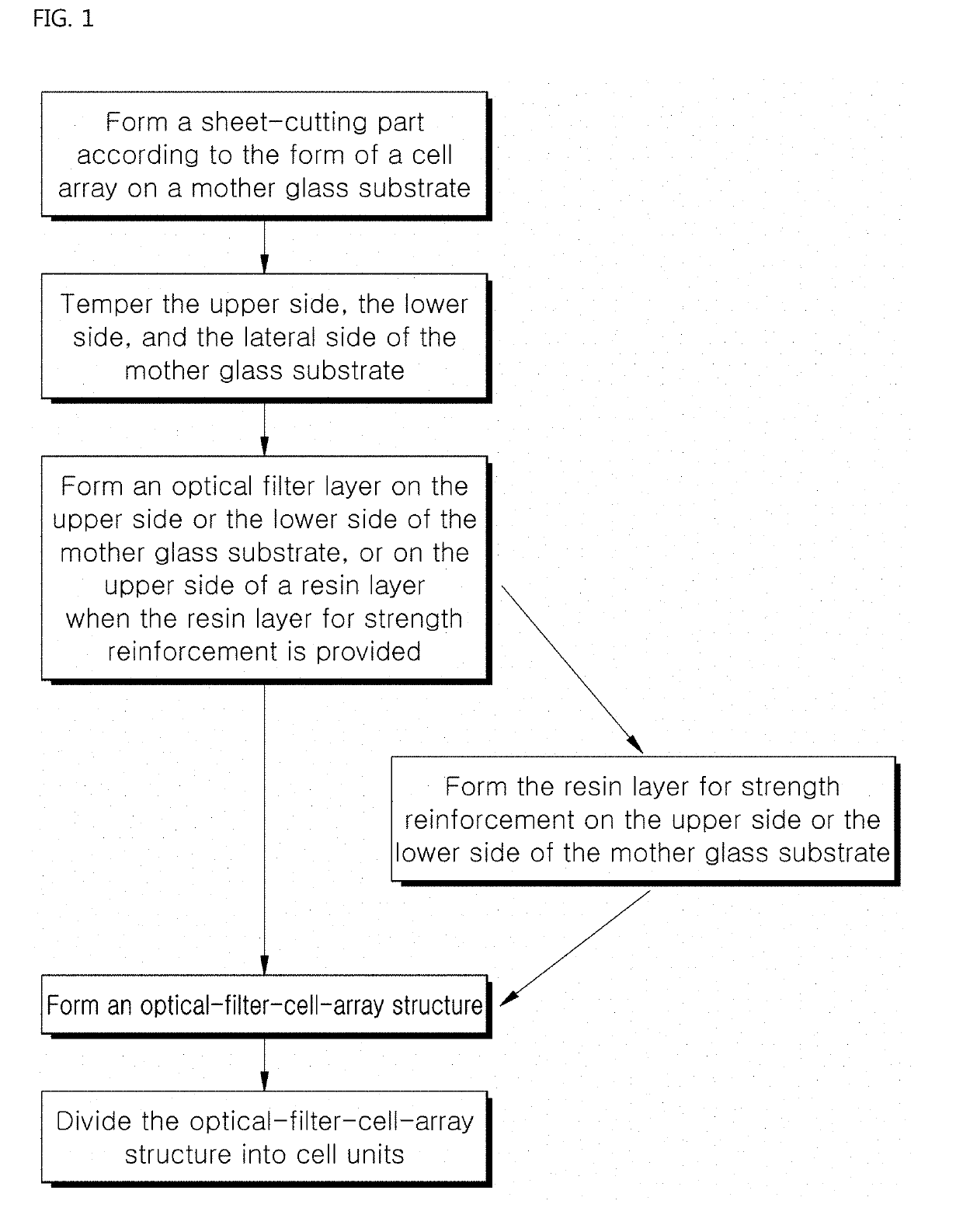
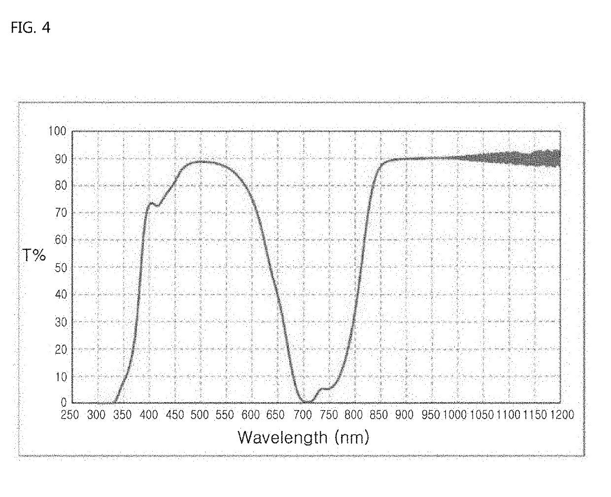
[0042]The present invention provides an optical filter using a tempered glass substrate to reinforce the strength thereof. In the case of the optical filter, the glass substrate is tempered and processed while being maintained in a sheet state, and an optical filter layer is formed on the upper side or the lower side of the glass substrate, thus blocking light in a specific wavelength.

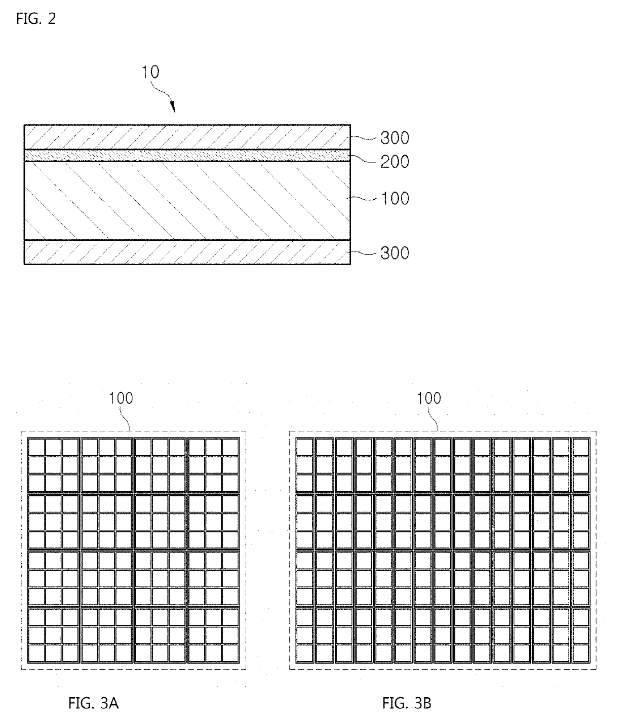
[0043]In particular, the optical filter according to the present invention is provided in the form of a cell array structure, thus preventing undesirable removal of optical filter cells provided in a sheet state and adjusting the interval between the optical filter cells or the shape of the cell unit according to the product specification, thereby providing an optical-filter-cell-array structure that is easy to store or supply.

[0044]Further, in the present invention, a resin layer for strength reinforcement is formed between the glass substrate and the optical filter layer, thus further reinforcing the...


PUM

PropertyMeasurementUnit
thicknessaaaaaaaaaa
thicknessaaaaaaaaaa
temperatureaaaaaaaaaa

Abstract

Disclosed is an optical-filter-cell-array structure and a method of manufacturing the same. An optical filter which includes an optical filter layer for blocking light of a specific wavelength formed on an upper side or a lower side of a tempered glass substrate is provided in the form of a cell array. The method includes forming a sheet-cutting part according to the form of a cell array on a mother glass substrate, tempering the mother glass substrate so that a lateral side of the mother glass substrate is tempered through the sheet-cutting part while an upper side and a lower side of the mother glass substrate are tempered, and forming an optical filter layer on the upper side or the lower side of the mother glass substrate.

Description

BACKGROUND OF THE INVENTION1. Field of the Invention[0001]The present invention relates to an optical-filter-cell-array structure and a method of manufacturing the same, and more particularly to an optical-filter-cell-array structure which has reinforced strength by providing an optical filter using a tempered glass substrate, and a method of manufacturing the same.2. Description of the Related Art[0002]An optical filter is an apparatus for selectively transmitting a band of a specific wavelength or preventing transmission thereof, and is provided by forming an optically designed multi-layered film on a substrate.[0003]Optical filters are used in various fields, and in particular are widely used to control the wavelength of light received by an image pickup lens of a camera.[0004]Generally, solid-state image pickup devices such as CCD or CMOS, which convert light into electric signals, are used in video cameras, digital cameras, or cameras of smart phones. The solid-state image pick...

Claims


Application Information

Patent Timeline
Patent Type & Authority Applications(United States)
IPC IPC(8): G02B5/20G02B5/26G02B1/14C03C3/04C03C21/00C03C17/32
CPCG02B5/208G02B5/26G02B1/14C03C3/04C03C21/002C03C17/32C03C2217/70G02B5/201C03C17/42C03C2217/445C03C2217/485C03B27/03G02B5/223G02B5/226
Inventor PARK, DEOK YOUNGHWANG, JAE YOUNGKIM, HAK CHULKIM, HYUNHOHA, TEA JOOLEE, JONGHWA
Owner UTI INC
Learn More