Supercharge Your Innovation With Domain-Expert AI Agents!

Floating horizontal tubular photobioreactor system with integrated manifolds for housing pumping and process monitoring and control devices

a photobioreactor and tubular technology, applied in biomass after-treatment, waste based fuel, biofuels, etc., can solve the problems of limited number of algae, low productivity of open systems, water evaporation and contamination in open systems,

Inactive Publication Date: 2019-06-27
WELCH MICHAEL +3
View PDF1 Cites 0 Cited by
  • Summary
  • Abstract
  • Description
  • Claims
  • Application Information

AI Technical Summary

Benefits of technology

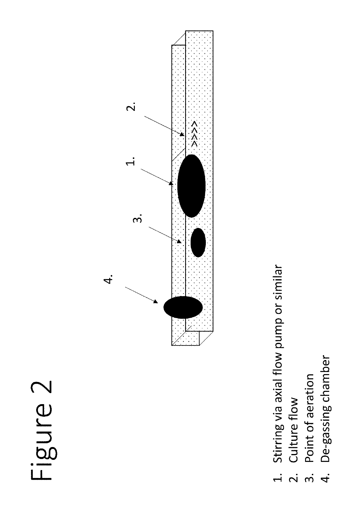
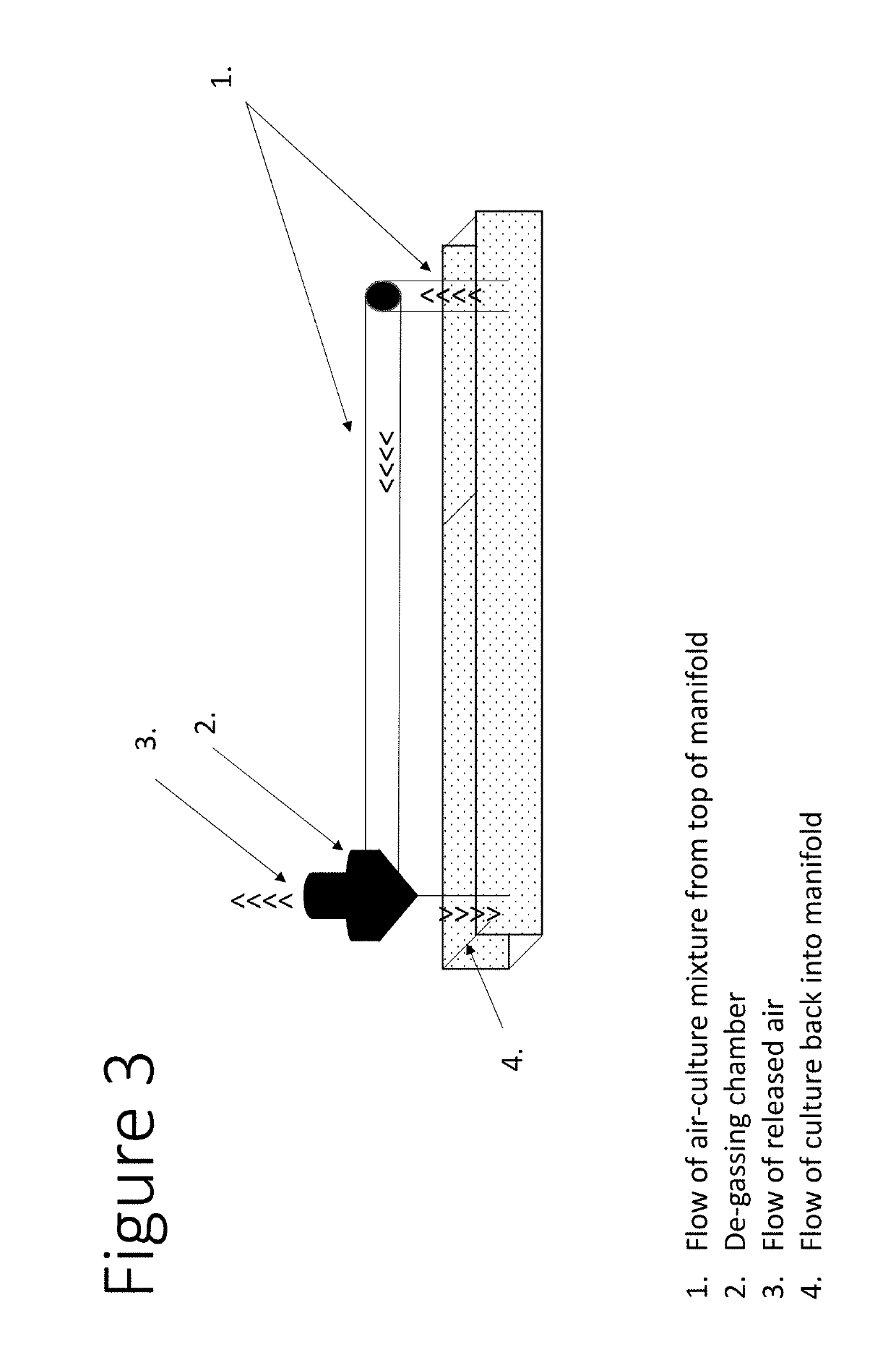
The present invention introduces two rigid manifolds into a floating horizontal tubular photobioreactor system as a means to improve mixing and aeration for the algae culture, allow the system to float, and house all necessary peripheral equipment. The rigid manifolds provide a comprehensive solution for mixing, aeration, degassing, and process monitoring and control. Additionally, the height of the rigid manifold out of the water can be adjusted to increase pressure inside the tubes to the appropriate level.

Problems solved by technology

These open systems are susceptible to water evaporation and contamination by foreign algae, protozoa, parasites or other microorganisms.
Thus, only a very limited number of algae with very specific growth characteristics can be cultivated in open systems.
In addition to being susceptible to contamination, open systems demonstrate low productivity.
This results in a high production cost of algae.
They also achieve usually only low biomass densities which results in high cost for pumping / treating the required water, harvesting and downstream processing.
Depending on the area of application, the production costs may be too high and not economical.
For example, the production costs of algae for use in the energy sector are too high to be profitable.
However, photobioreactors have investment costs that are too high for many applications to achieve economical production of algae cell mass.
While the flexibility of the horizontal reactor gives rise to a number of advantages, it also creates some major challenges that prohibit commercial use.
A major challenge is keeping a steady flow of water in the reactor to ensure adequate mixing.
This distorts the cross-sectional shape of the flow, leading to energy dissipation and and flow failure due to insufficient flow velocity.
In addition to mixing, aeration is another challenge in a flexible reactor.

Method used


Image

  • Floating horizontal tubular photobioreactor system with integrated manifolds for housing pumping and process monitoring and control devices
  • Floating horizontal tubular photobioreactor system with integrated manifolds for housing pumping and process monitoring and control devices
  • Floating horizontal tubular photobioreactor system with integrated manifolds for housing pumping and process monitoring and control devices

Examples


Embodiment Construction

[0019]In order that the invention herein described may be fully understood, the following detailed description is set forth.

[0020]Unless defined otherwise, all technical and scientific terms used herein have the same meaning as those commonly understood by one of ordinary skill in the art to which this invention belongs. Although methods and materials similar or equivalent to those described herein can be used in the practice or testing of the present invention, suitable methods and materials are described below. The materials, methods and examples are illustrative only, and are not intended to be limiting. All publications, patents and other documents mentioned herein are incorporated by reference in their entirety.

[0021]Throughout this specification, the word “comprise” or variations such as “comprises” or “comprising” will be understood to imply the inclusion of a stated integer or groups of integers but not the exclusion of any other integer or group of integers.

[0022]The term “...


PUM

PropertyMeasurementUnit
flexibleaaaaaaaaaa
gravityaaaaaaaaaa
densityaaaaaaaaaa

Abstract

This invention relates to a floating horizontal tubular photobioreactor system comprising a photosynthetically active area made of flexible tubes connected to rigid manifolds with an integrated system for mixing, aeration and degassing. This invention further relates to methods of using the floating photobioreactor system.

Description

FIELD OF THE INVENTION[0001]This invention relates to a floating horizontal tubular photobioreactor system comprising a photosynthetically active area made of tubes from plastic film integrated with manifolds at the ends which enable the system to float and house all auxiliary equipment required for pumping, aerating, degassing, and process monitoring and control. This invention further relates to methods of using the floating photobioreactor system.BACKGROUND OF THE INVENTION[0002]The majority of today's photosynthetic algae production is practiced in open systems (“open ponds”). These open systems are susceptible to water evaporation and contamination by foreign algae, protozoa, parasites or other microorganisms. Thus, only a very limited number of algae with very specific growth characteristics can be cultivated in open systems. For example, the species Dunaliella grows in extremely salty water, in which hardly any other organisms can grow, and as such, it can be cultivated in an...

Claims


Application Information

Patent Timeline
Patent Type & Authority Applications(United States)
IPC IPC(8): C12M1/00C12M1/12C12M1/09C12M1/06C12P13/04C12P7/06C12P5/02C12P3/00C12P7/64C12P21/00
CPCC12M21/02C12M23/06C12M21/12C12M23/56C12M23/26C12M29/20C12M29/00C12M27/02C12M41/06C12P13/04C12P7/065C12P5/023C12P3/00C12P7/6409C12P21/00C12M23/40C12M27/00C12M29/06C12P7/6463Y02E50/10Y02E50/30
Inventor WELCH, MICHAELWALMSLEY, LAWRENCEMEISER, ANDREASPHILIPPIDIS, GEORGE
Owner WELCH MICHAEL
Features
  • R&D
  • Intellectual Property
  • Life Sciences
  • Materials
  • Tech Scout
  • Unparalleled Data Quality
  • Higher Quality Content
  • 60% Fewer Hallucinations
Learn More