Microfluidic Movement Control Method Utilizing Light
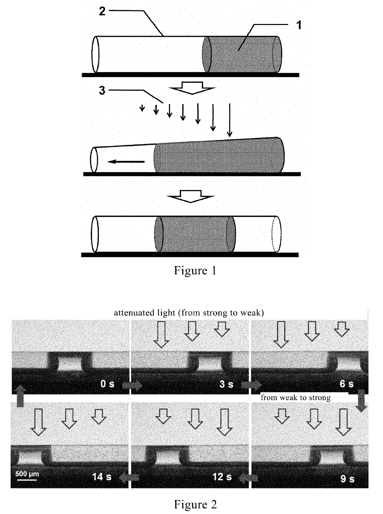
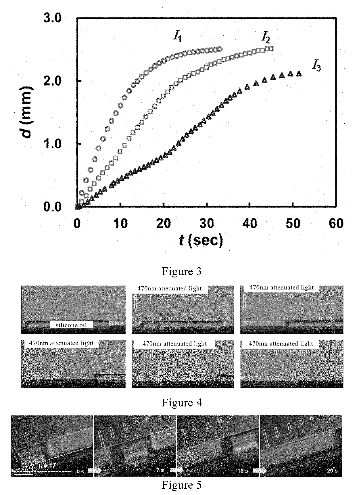
a microfluidic and light-emitting technology, applied in fluid controllers, mechanical instruments, laboratory glassware, etc., can solve the problems of limiting the movement of micro-liquid to a large extent, serious limiting its practical application, and the resistance of the three-phase contact line to the light-induced wetting gradien
- Summary
- Abstract
- Description
- Claims
- Application Information
AI Technical Summary
Benefits of technology
Problems solved by technology
Method used
Image
Examples
preparation example 1 preparation
of Microchannel Actuator
[0142]1. Preparation of the Channel Wall Material of the Microchannel Actuator
[0143]The structure of this material is shown below.
[0144]The specific preparation method refers to the procedure of Example 1 of CN103087296A.
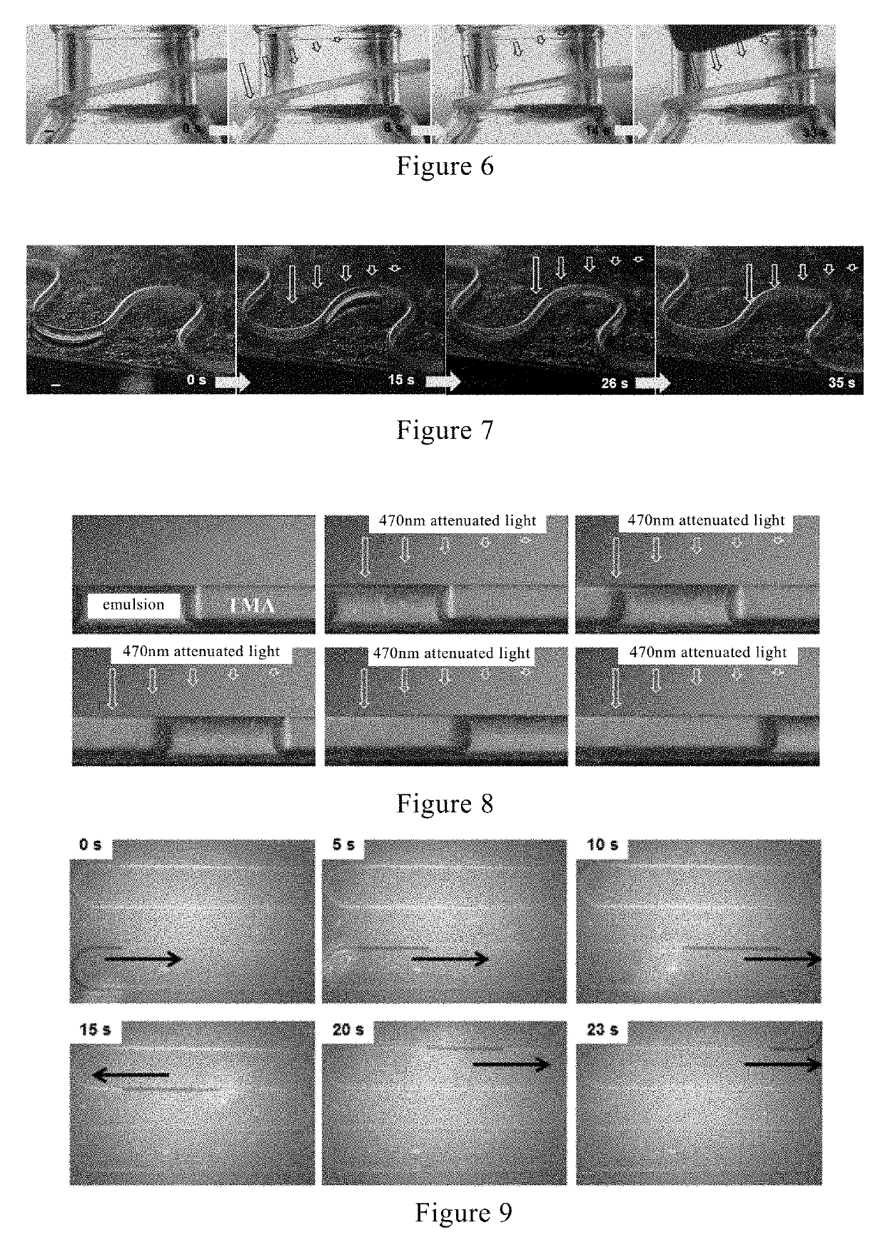
[0145]2. Preparation of a Straight, Serpentine, and Spiral Microchannel Actuators by Using the Above Wall Material
[0146]Preparation Steps
[0147]2.1 Straight Microchannel Actuator
[0148]A solution of PCmABn in dichloromethane (0.1-20% by weight) was sucked into a straight glass capillary, and then the capillary filled with the solution was placed in an oven until the solvent was evaporated. The inner wall of the capillary was uniformly covered by PCmABn. The straight capillary coated with PCmABn on the inner wall was placed in hydrofluoric acid to etch away the glass to obtain a straight microchannel actuator.
[0149]2.2 Serpentine Microchannel Actuator
[0150]A solution of PCmABn in dichloromethane (0.1-20% by weight) was sucked into a serpentine g...
preparation example 2 preparation
of Microchannel Actuator
[0160]1. Preparation of the Channel Wall Material of the Microchannel Actuator
[0161]The structure of this material is shown below.
[0162]The specific preparation method refers to the procedure of Example 1 of CN103087296A.
[0163]M mole of CF monomer was mixed with n mole of CAB monomer in a Hiddink bottle, and a sufficient amount of dichloromethane was added to dissolve them. At 40° C., a certain amount of Grubbs second generation catalyst was added to initiate polymerization. After 10 hr, the polymerization was terminated using vinyl ether to obtain P(CmABn)x(CpBPq)y.
[0164]2. Preparation of a Straight, Serpentine, Y-Shaped and Composite Microchannel Actuators by Using the Above Wall Material
[0165]Preparation Steps
[0166]2.1 Straight Microchannel Actuator
[0167]A solution of P(CmABn)x(CpBPq)y in dichloromethane (0.1-30% by weight) was sucked into a straight glass capillary, and then the capillary filled with the solution was placed in an oven until the solvent wa...
preparation example 3 preparation
of Microchannel Actuator
[0174]1. Preparation of the Channel Wall Material of the Microchannel Actuator
[0175]The structure of this material is shown below.
[0176]The specific preparation method refers to the procedure of Example 1 of CN103087296A.
[0177]A certain molar amount of the azo group-containing norbornene monomer CAB was added to the Hiddink bottle, and a sufficient amount of methylene chloride was added to dissolve it. A certain amount of Grubbs second generation catalyst was added at 40° C. to initiate polymerization. After 10 hours, the polymerization was terminated using vinyl ethyl ether to obtain PNmABn.
[0178]2. Preparation of a Straight, Serpentine, and Y-Shaped Microchannel Actuator by Using the Above Wall Material
[0179]Preparation Steps
[0180]2.1 Straight Microchannel Actuator
[0181]A solution of PNmABn in dichloromethane (0.1-30% by weight) was sucked into a straight glass capillary, and then the capillary filled with the solution was placed in an oven until the solven...
PUM
| Property | Measurement | Unit |
|---|---|---|
| inner diameter | aaaaa | aaaaa |
| inner diameter | aaaaa | aaaaa |
| outer diameter | aaaaa | aaaaa |
Abstract
Description
Claims
Application Information
 - R&D
- Intellectual Property
- Life Sciences
- Materials
- Tech Scout
- Unparalleled Data Quality
- Higher Quality Content
- 60% Fewer Hallucinations
Browse by: Latest US Patents, China's latest patents, Technical Efficacy Thesaurus, Application Domain, Technology Topic, Popular Technical Reports.
© 2025 PatSnap. All rights reserved.Legal|Privacy policy|Modern Slavery Act Transparency Statement|Sitemap|About US| Contact US: help@patsnap.com


