
Attachment structure for vehicle motor, in-vehicle equipment, and brushless motor

a technology for vehicle motors and attachment structures, which is applied in the direction of magnetic circuit rotating parts, braking systems, magnetic circuit shapes/forms/constructions, etc., can solve the problems of motor vibration, structural deterioration, and lowering performance, so as to reduce performance, reduce noise, and cause structural deterioration

Active Publication Date: 2019-08-01
DENSO CORP
View PDF8 Cites 4 Cited by
  • Summary
  • Abstract
  • Description
  • Claims
  • Application Information

AI Technical Summary

Benefits of technology

The invention aims to address the issue of motor vibration and noise in in-vehicle devices caused by the output side of the motor being fixed to the main body of the device. They also aim to improve redundancy in the motor design to prevent the heat from affecting the coil of another set.

Problems solved by technology

Thus, the motor has a tendency to be vibrated by the vibration produced when the vehicle travels or by the vibration of the in-vehicle device.
As a result, the vibration generates noise, lowers the performance, and causes structural deterioration.
Thus, when the coil of one of the sets is heated such that the coating of the coil is melted or carbonized, the heat will easily affect the coil of the other set.

Method used


Image

  • Attachment structure for vehicle motor, in-vehicle equipment, and brushless motor
  • Attachment structure for vehicle motor, in-vehicle equipment, and brushless motor
  • Attachment structure for vehicle motor, in-vehicle equipment, and brushless motor

Examples


first embodiment

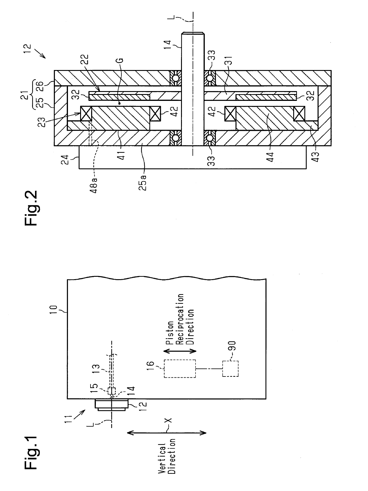
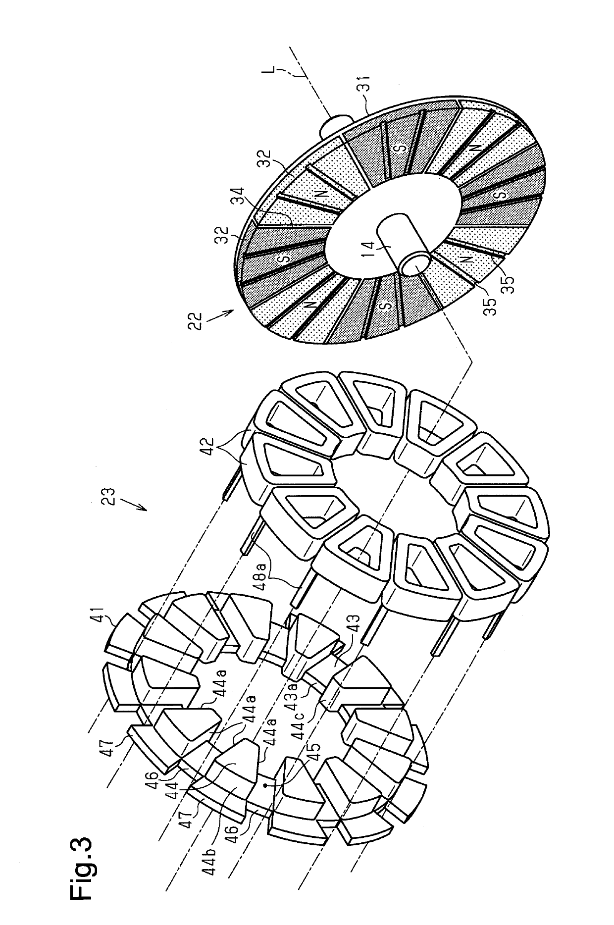
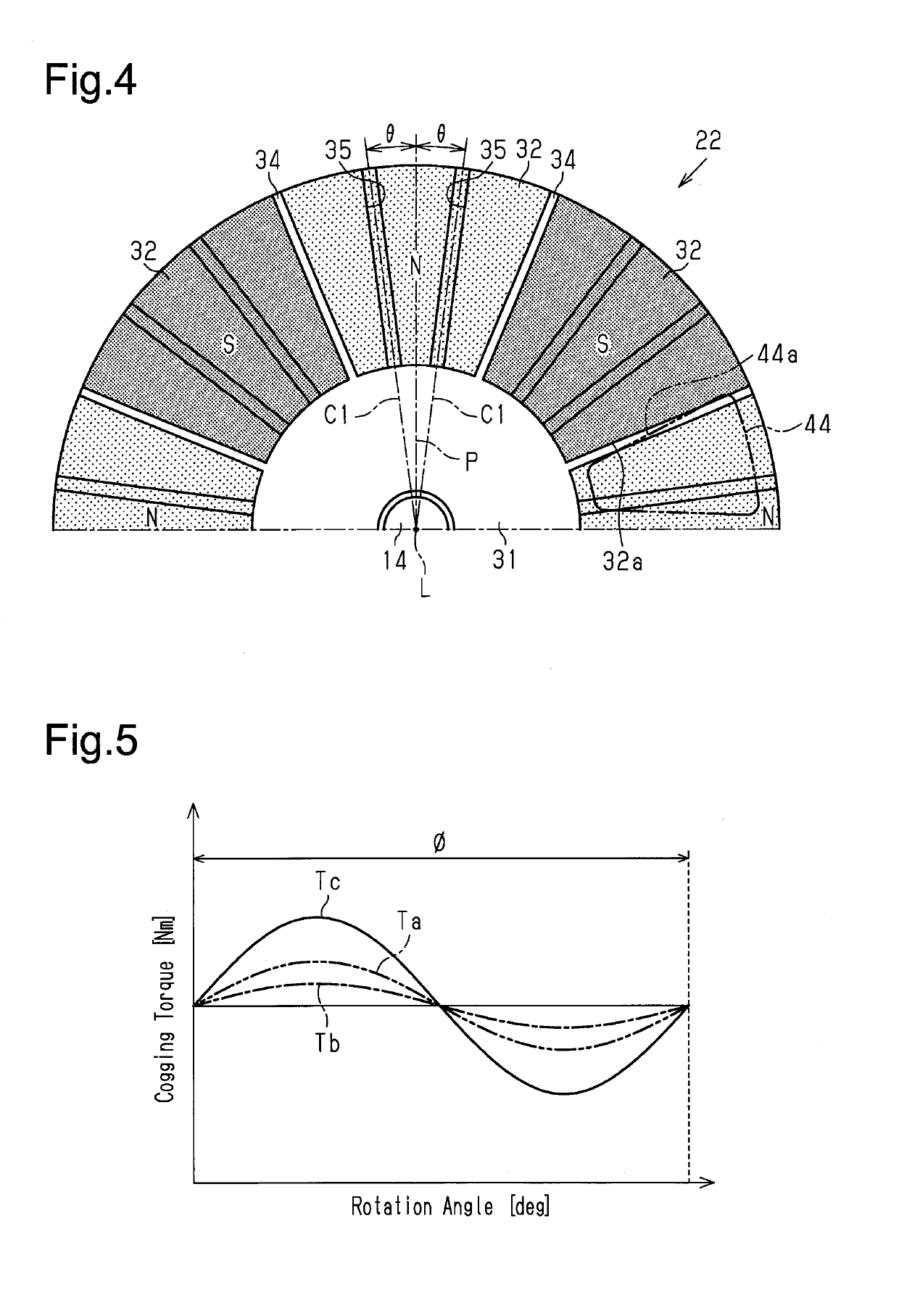
[0041]Hereinafter, a first embodiment of a vehicle motor attachment structure and an in-vehicle device will be described. In the present embodiment, a variable valve timing device of an internal combustion engine will be described as an example of the in-vehicle device. In the drawings, elements are illustrated for simplicity and clarity and have not necessarily been drawn to scale.

[0042]As shown in FIG. 1, a variable valve timing device 11, which is mounted on an internal combustion engine 10 of a vehicle, includes a motor 12 and is used to adjust a relative rotation phase of a camshaft 13 with respect to a crankshaft (not shown) in the internal combustion engine 10 based on the driving of the motor 12. More specifically, a rotation shaft 14 of the motor 12 is connected to the camshaft 13 for opening or closing an engine valve (not shown) through an adjustment mechanism 15. Then, the adjustment mechanism 15, which is operated by the rotation torque output from the motor 12, is used...

second embodiment

[0082]Hereinafter, a second embodiment of a vehicle motor attachment structure and an in-vehicle device will be described. In the present embodiment, an electric power steering device will be described as an example of the in-vehicle device. In the drawings, elements are illustrated for simplicity and have not necessarily been drawn to scale. Further, same reference numerals are given to those components that are the same as the corresponding components of the first embodiment. The description centers on parts differing from the first embodiment.

[0083]As shown in FIG. 6, an electric power steering device 50 of the present embodiment is of a column assist type. The electric power steering device 50 includes a steering shaft 52, to which a steering wheel 51 is connected, and a motor 54, which is connected to the steering shaft 52 through a speed reduction mechanism 53. The motor 54 is controlled in accordance with a vehicle speed or a steering torque detected by a torque sensor (not s...


PUM


Abstract

An attachment structure for a vehicle motor is applied for the purpose of attaching a vehicle motor to in-vehicle equipment. The attachment structure for a vehicle motor is provided with an axial gap motor that includes a rotor and a stator facing each other in the axial direction. The motor is attached to the in-vehicle equipment in a mode in which the axial direction is perpendicular to the vertical direction.

Description

TECHNICAL FIELD[0001]The present invention relates to a motor attachment structure provided in an in-vehicle device.BACKGROUND ART[0002]In the prior art, various in-vehicle devices including a motor serving as a drive source are mounted on a vehicle. For example, patent document 1 discloses a variable valve timing device as an example of an in-vehicle device that adjusts a relative phase of a camshaft and a crankshaft, which determines an opening / closing timing of an intake valve or an exhaust valve of an internal combustion engine, based on a driving force of a motor.[0003]Further for example, as described in, for example, patent document 2, in the prior art, a brushless motor for a vehicle includes, a stator including coils, a rotor opposing the stator, and a drive circuit connected to the coils of the stator. When current is supplied from the drive circuit to the coil of the stator and a rotating magnetic field is generated at the coils of the stator, the rotor is rotationally dr...

Claims


Application Information

Patent Timeline
Patent Type & Authority Applications(United States)
IPC IPC(8): F01L1/352B60T13/74F16D65/18H02K1/27H02K21/24H02K5/24H02K7/14F01P3/20
CPCF01L1/352B60T13/748F16D65/186H02K1/2793H02K21/24H02K5/24H02K7/14F01P3/20F01L2001/3522F01L2101/00F01L2810/03F01L2810/04F01L2820/01F01L2820/02F01L2820/032F01L2820/04F01P2005/046F01P2005/125F02D13/0219F16D2121/20H02K5/1732B60T13/741H02K29/03H02K2213/03H02K7/083H02K3/28F01L1/344F01L2301/00Y02T10/12H02K1/2795
Inventor YOKOYAMA, SEIYATSUCHIYA, TAKAHIROKATO, SHIGEMASAYAMADA, YOJIMIKAMI, KOJIHATTORI, AKIHISA
Owner DENSO CORP
Learn More