Chromatography System

Active Publication Date: 2019-08-01
PURIDIFY
View PDF0 Cites 6 Cited by
  • Summary
  • Abstract
  • Description
  • Claims
  • Application Information

AI Technical Summary

Benefits of technology

[0050]wherein the flow guide comprises a pattern of channels providing flow paths from the inlet to different parts of the adsorbent chromatography medium along the width of the adsorbent chromatography medium, wherein the pattern of channels is provided so as to reduce a difference in arrival time and/or flow velocity of liquid reaching the adsorbent chromatography medium across the width of the adsorbent chromatography medium.
[005

Problems solved by technology

Yet, while the downstream purification processes have also received some research and development, improvements in this area have not matched those in the upstream.
Therefore there is a significant volume expansion event which can lead to mixing or separation of the incoming pulse.
These pulses of liquid can undesirably mix with each other and/or be poorly distributed across the chromatographic media.
Mixing and poor distribution can lead to the pulse that is introduced to the chromatographic system exiting in a larger volume/time than at which it was introduced resulting in negative performance effects such as product dilution and/or increased buffer usage.
Additionally, poor distribution of the pulse can result in poor utilisation of the chromatography media due to the failure of the pulse to come into contact with the entirety of the chromatographic media.
Mixing of liquid from different pulses and/or poor distribution has the following negative impacts on performance as it i) reduces the resolution of the separation ii) requires an increase in the liquid volume of each pulse to ensure adequate contact with the media iii) reduces the concentration of the eluted product and iv) reduces the effective capacity of the chromatographic media due to under-utilisation of binding sites.
At industrial scale buffers represent a

Method used


Image

  • Chromatography System
  • Chromatography System
  • Chromatography System

Examples


Example

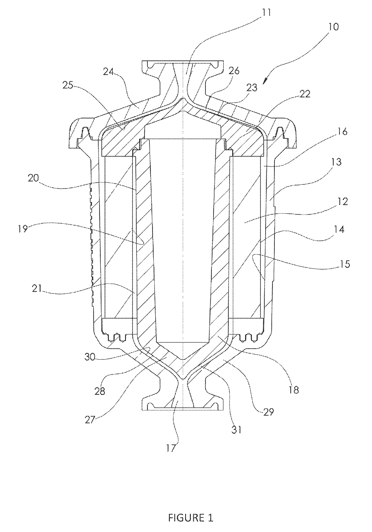
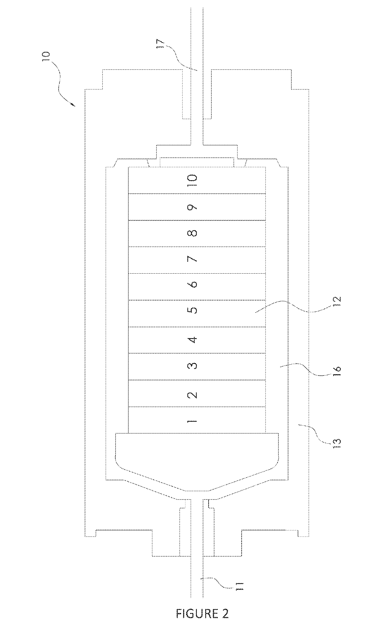
[0097]FIG. 1 is a schematic diagram of a chromatography system 10 according to an embodiment of the present invention. FIG. 1 is a cross-sectional view of the chromatography system 10. The chromatography system 10 may be called a chromatographic unit or a chromatography cartridge, for example.

[0098]As depicted in FIG. 1, the chromatography system 10 comprises an inlet 11. The inlet 11 is the entry point for fluids (such as buffers, suspensions or solutions comprising proteins, for example) into the chromatography system 10. In use, the chromatography system 10 may be oriented opposite to the orientation shown in FIG. 1, namely with the inlet 11 at the bottom of the chromatography system 10. Pulses of liquid are pumped upwards through the inlet 11. This orientation has advantages of removing trapped air from the chromatography system 10, as explained below. Alternatively, the chromatography system 10 may be oriented as shown in FIG. 1, namely with the inlet 11 at the top of the chrom...


PUM


Abstract

A chromatography system for at least one of tangential flow chromatography and lateral flow chromatography comprising: an inlet; a functionalised adsorbent chromatography medium downstream of the inlet; an outlet downstream of the adsorbent chromatography medium; and a flow guide downstream of the inlet and upstream of the adsorbent chromatography medium and configured to distribute a flow of a liquid from the inlet across a width of the adsorbent chromatography medium; wherein the flow guide comprises a pattern of channels providing flow paths from the inlet to different parts of the adsorbent chromatography medium along the width of the adsorbent chromatography medium, wherein the pattern of channels is provided so as to reduce a difference in arrival time and/or flow velocity of liquid reaching the adsorbent chromatography medium across the width of the adsorbent chromatography medium.

Description

FIELD OF THE INVENTION[0001]The present invention relates to a chromatography system, a method of manufacturing a chromatography system, a method of performing tangential flow filtration and at least one of tangential flow chromatography and lateral flow chromatography, and a process for isolating one or more biological molecules from a mobile phase. More particularly, the present invention relates to chromatography using a functionalised adsorbent chromatography medium which may be suitable for isolating biological molecules from mobile phases.BACKGROUND TO THE INVENTION[0002]The biotechnology market is the fastest growing sector within the world pharmaceutical market, accounting for 20% ($153bn) of all market sales in 2012. This growth from 10% of the market share in 2002 is set to grow by 41% between 2012 and 2018 from $153bn to $215bn and in 2016 is at $200bn. There are currently around 200 monoclonal antibody (MAb) products on the market, and with over 1000 in clinical trials, ...

Claims


Application Information

Patent Timeline
IPC IPC(8): G01N30/38G01N30/60G01N30/84
CPCG01N30/38G01N30/6017G01N30/84G01N2030/386
Inventor WILLIAMS, MICHAELROBERTS, IWANHARDICK, OLIVERTOWNSEND, MATTHEWMORRIS, CHRISTOPHERSUBRATTY, SHAMEER
Owner PURIDIFY
Why Eureka
Try Eureka