Toner and method for producing the toner

a technology of toner and toner particles, applied in the field of toner, can solve the problems of insufficient resistance to stress, and difficulty in suppressing etc., and achieve the effect of difficult to suppress cracking and chipping of toner particles

Active Publication Date: 2019-08-01
CANON KK
View PDF1 Cites 8 Cited by
  • Summary
  • Abstract
  • Description
  • Claims
  • Application Information

AI Technical Summary

Benefits of technology

[0009]With the simple control of the average diameter of bubbles in the shell layer, as in the toner disclosed in Japanese Patent No. 6068312, it is somewhat difficult to suppress cracking and chipping of the toner particles caused by the presence of bubbles in the vicinity of the surface of the toner.

Problems solved by technology

With the simple control of the average diameter of bubbles in the shell layer, as in the toner disclosed in Japanese Patent No. 6068312, it is somewhat difficult to suppress cracking and chipping of the toner particles caused by the presence of bubbles in the vicinity of the surface of the toner.
When the size and proportion of voids are simply specified, as in the toner disclosed in Japanese Patent No. 5990881, it is somewhat difficult to suppress cracking and chipping of the toner particle caused by the presence of bubbles in the vicinity of the surface of the toner particle.
When large voids are present in the vicinity of the surface of the toner particle, as in the toner disclosed in Japanese Patent No. 5493612, the resistance to stress is not sufficient and it is somewhat difficult to prevent deterioration of image quality.
Further, in any of the above-mentioned disclosures, it is somewhat difficult to suppress exudation of wax due to chipping in the vicinity of the surface layer of a toner particle.

Method used


Image

  • Toner and method for producing the toner
  • Toner and method for producing the toner
  • Toner and method for producing the toner

Examples


example 1

[0391]A toner was produced by the following procedure.

Preparation of Pigment Dispersion Composition

[0392]

Styrene21.76partsC.I. Pigment Red 1221.98partsC.I. Pigment Red 1501.13partsCharge control agent0.44part(Bontron E 88, manufactured by Orient ChemicalIndustries, Ltd.)

[0393]A pigment dispersion composition was prepared by introducing these materials into an attritor (manufactured by Nippon Coke & Engineering Co., Ltd.), stirring with zirconia beads having a radius of 1.25 mm at 200 rpm for 180 min at 25° C., and then removing the zirconia beads.

[0394]Preparation of Polymerizable Monomer Composition

[0395]The following materials were charged into a container and mixed and dispersed at a peripheral velocity of 20 m / s by using T. K. HOMOMIXER (manufactured by Primix Corporation).

Pigment dispersion composition25.76partsStyrene14.55partsn-Butyl acrylate8.10partsPolyester resin2.22partsStyrene-methacrylic acid-methyl methacrylate-α-methyl5.33partsstyrene copolymer(Styrene / methacrylic aci...

examples 2 , 4 to 10

Examples 2, 4 to 10, and 12 to 25

[0480]Toners were produced in the same manner as in Example 1 and evaluated in the same manner as in Example 1, except that the conditions were changed to those shown in Table 1-1 and Table 1-2.

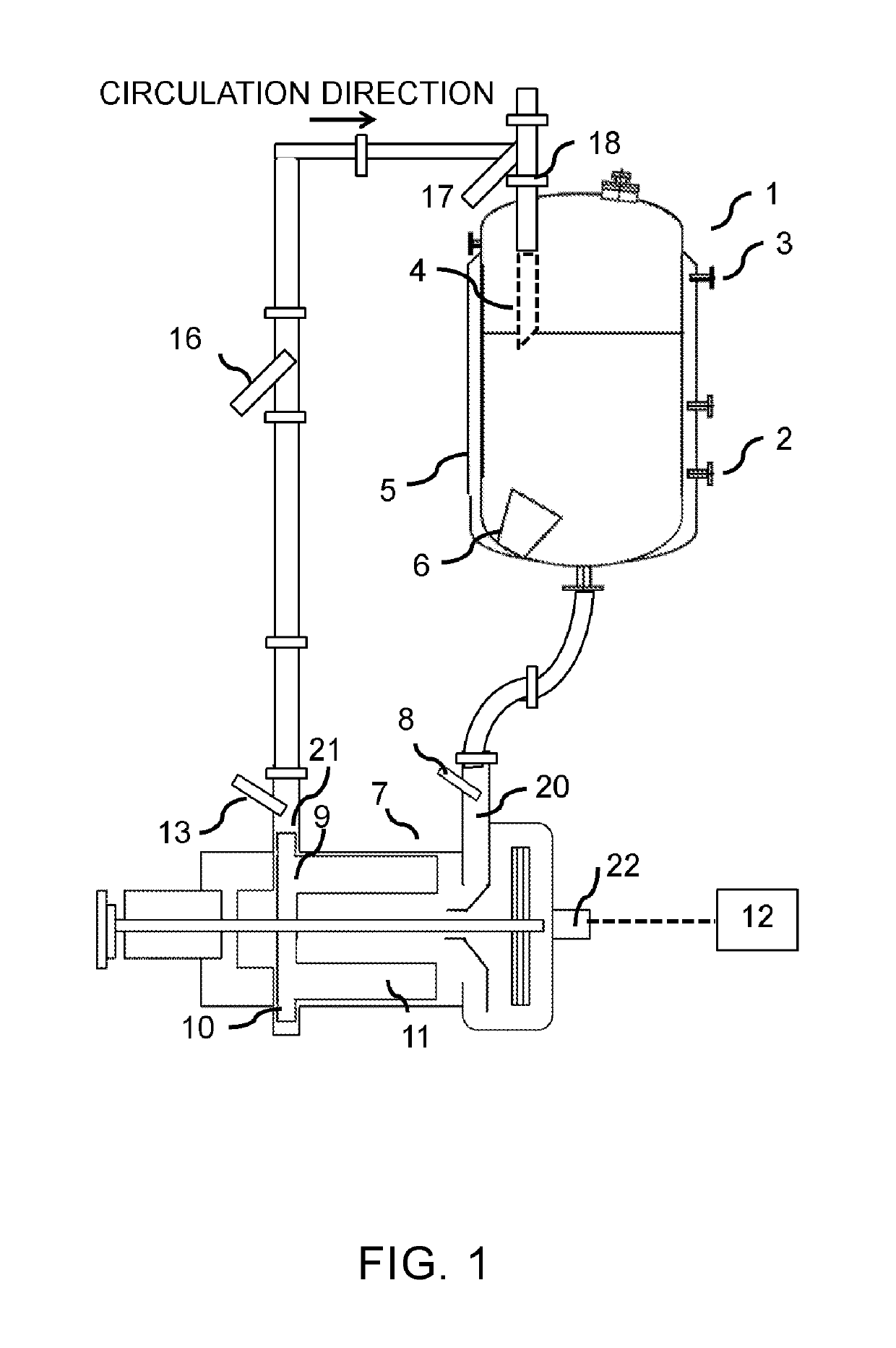
[0481]In Example 12, a toner was produced in the same manner as in Example 1 and evaluated in the same manner as in Example 1, except that the tank I was not provided with the inner nozzle 4.

[0482]In Example 13, a toner was produced in the same manner as in Example 1 and evaluated in the same manner as in Example 1, except that a defoaming pump (manufactured by Fushida Metal Industry Co., Ltd.) was used as the device 7 and gas-liquid separation by an impeller was not performed.

example 3

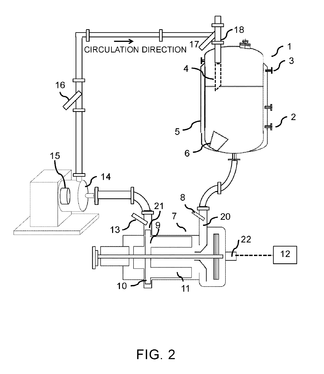
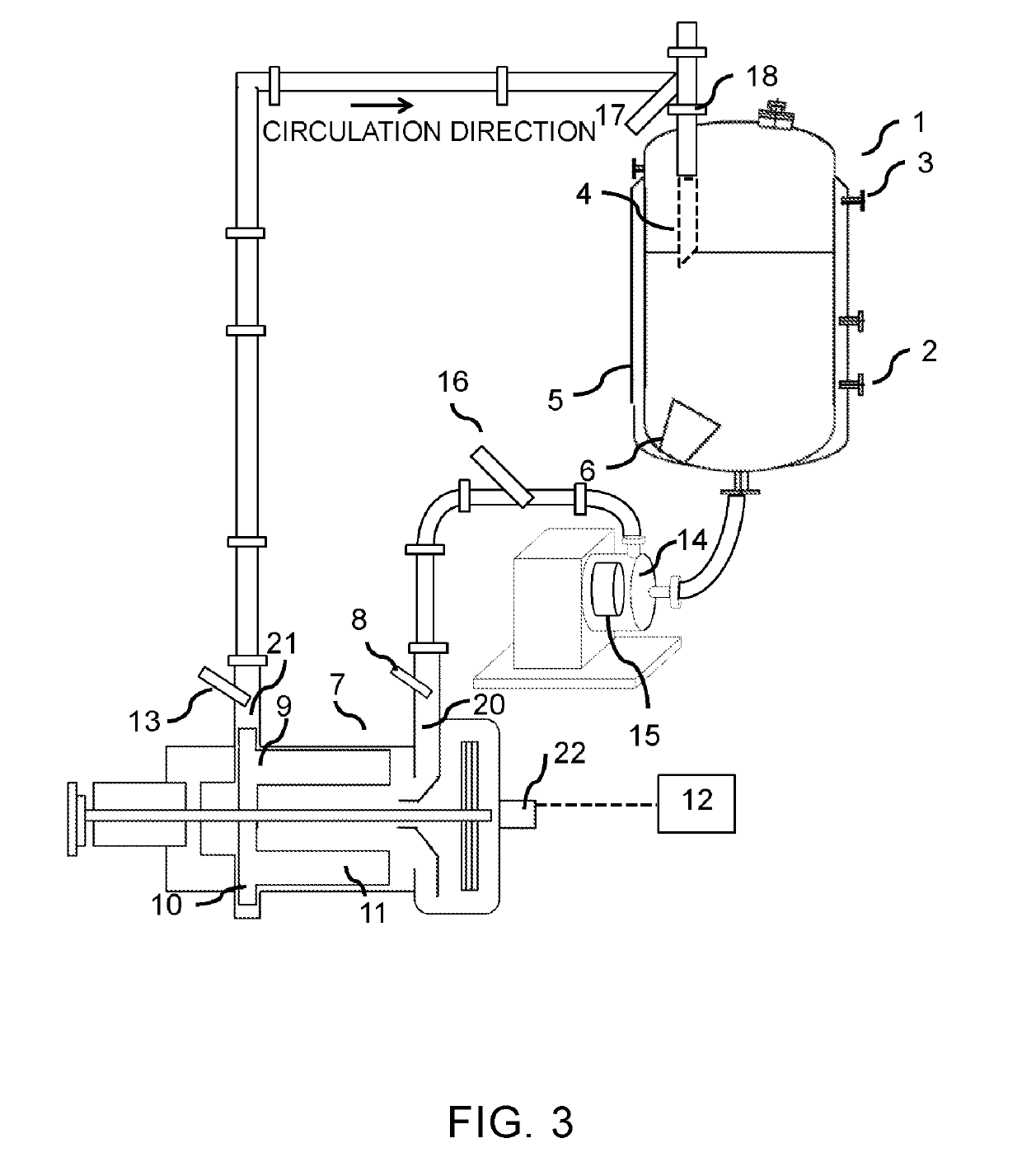
[0483]A toner was produced in the same manner as in Example 1 and evaluated in the same manner as in Example 1 except that the granulation system shown in FIG. 2 was used instead of the granulation system shown in FIG. 3 and the conditions were changed to those shown in Table 1-1.


PUM


Abstract

A toner has a toner particle including a binder resin, a colorant, and a wax, in which in a cross section of the toner particle observed under a scanning transmission electron microscope, a proportion of the number of toner particles having a void with a long diameter of 0.50 μm or less is 60 number % or more, and a proportion of the number of toner particles having a void in a region from an outline of the cross section of the toner particle inward to 1.00 μm in a total number of the toner particles having a void is 30 number % or less.

Description

BACKGROUND OF THE INVENTIONField of the Invention[0001]The present invention relates to a toner for visualizing an electrostatic charge image in an image forming method such as electrophotography, electrostatic printing, and magnetic recording, and to a method for producing the toner.Description of the Related Art[0002]In recent years, a demand has been created for printers and copying machines in which high-definition images are obtained by digitization and, at the same time, the speed of printing or copying is increased, and no image defects appear even in long-term use and use under a high-temperature and high-humidity environment or a low-temperature and low-humidity environment.[0003]One of the causes of image defects is that because toner particles including a large number of voids are used for electrophotography, the toner particles crack owing to the shear occurring between functional parts, which results in fusion of the particles to parts in the cartridge and occurrence of...

Claims


Application Information

Patent Timeline
Patent Type & Authority Applications(United States)
IPC IPC(8): G03G9/08G03G9/087
CPCG03G9/0821G03G9/0819G03G9/08782G03G9/0806G03G9/08797G03G9/083G03G9/0825
Inventor INOUE, KOKITSUJINO, TAKESHIHASHIMOTO, YASUHIROASAOKA, JUNYASASANO, YUUKATAYAMA, KENTAAMANO, SHOTA
Owner CANON KK
Why Eureka
Try Eureka