
Hybrid VTOL Aerial Vehicle

a hybrid and aerial vehicle technology, applied in the direction of vertical landing/take-off aircraft, efficient propulsion technologies, transportation and packaging, etc., can solve the problems of high temperature of direct-jet thrust system, high risk for ground personnel, and high risk of ground personnel

Active Publication Date: 2019-08-22
NEFF WILLIAM J
View PDF2 Cites 20 Cited by
  • Summary
  • Abstract
  • Description
  • Claims
  • Application Information

AI Technical Summary

Benefits of technology

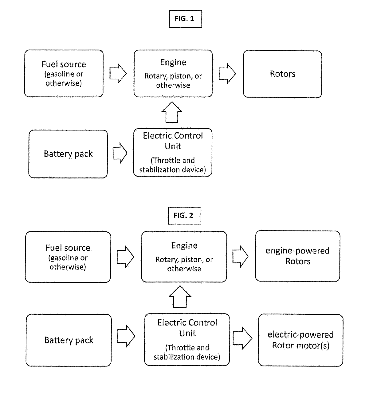
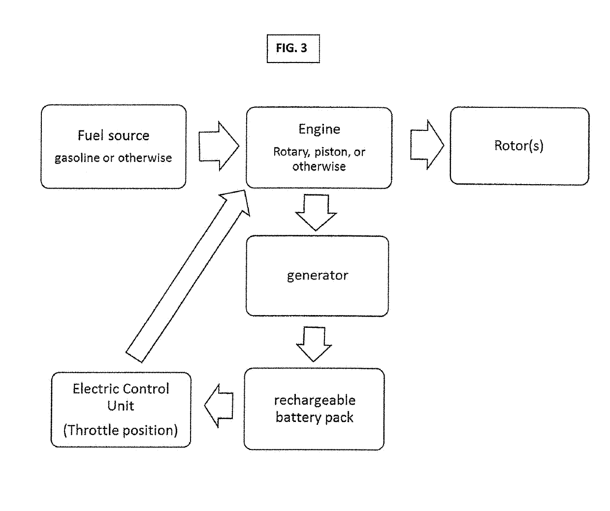
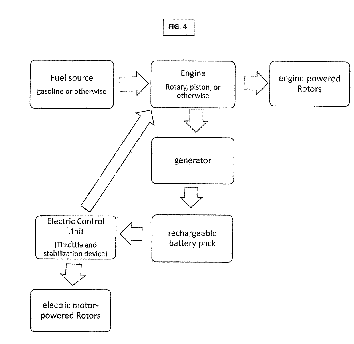
The patent text describes various configurations and methods for manned or unmanned aerial vehicles that use multiple engines and / or electric motors to generate thrust and fly. The vehicles may have electronic speed controls and generators to provide power to the engines and motors. The vehicles may also have a rechargeable battery and a gyroscope or computer to stabilize flight. The technical effects of the patent text include improved stability, efficiency, and control of the aerial vehicle's power system.

Problems solved by technology

These vehicles are inherently high-speed aircraft, with engines sized (as a result of their inefficiency for VTOL propulsion) for very high power levels.
This is dangerously high for ground personnel, and it makes it unlikely that these vehicles could be operated from any but carefully prepared reinforced surfaces.
Additionally, the exhaust temperatures associated with direct-jet-thrust systems is very high—up to 1200° F.—thus posing an additional problem for near-ground operations.
Moreover, the sheer size of the unprotected rotor disk leads to handling and safety issues with blade strike in obstacle-rich environments.
As a result of this configuration, rotorcraft are mechanically complex and are subject to large vibratory loads as loading changes on the rotating blades.
Torques generated by the rotor must be balanced, either by a tail rotor or another main rotor, further increasing complexity and weight.
Tilt-rotors operate at higher thrust loading (typically 40-70 lb / ft2), with consequently higher power requirements and downwash velocity.
Power is applied to the fans by a mechanically complex transmission and shafting arrangement.
The flying platforms were limited in control in VTOL and forward flight, depending on rotor blade pitch or throttle for vertical control and vanes in the fan flow for yaw and roll control.
These vehicles had relatively low maximum speeds (less than 100 knots) and became difficult to control at high speeds due to aerodynamic problems with the ducts in axial cross-flow.
These aircraft are mechanically complex, with transmission and gearboxes to distribute engine power to the fans and rotors.
Maximum speeds for these vehicle is very limited—only 80-100 knots.
In striving to find an aerial vehicle that is suitable for civilian commuter use, the jet-thrust VTOL systems are less desirable due to exorbitant cost, need for a special tarmac capable of sustaining the high temperature from the thrust, as well as the potential danger imposed by being nearby.
The helicopter and tilt-rotor systems also pose problems due to high cost and potential danger of being in vicinity of the exposed rotors.
Having an all-electric (only battery powered) quadcopter large enough to carry a person (e.g., Ehang 184 or Hoversurf's Scorpion-3) proposes an option as a daily commuter vehicle for short distance travel; however the all-electric format may hamper the effectiveness of this vehicle due to limited flight time.
As shown supra, today VTOL applications are confined to large and very expensive aerial vehicles such as generally seen in the military or lightweight unmanned-aerial-vehicle (UAVs) that are commonly referred to as battery powered radio-controlled quadcopters or drones.
The large aerial vehicles can transport people, but require a large footprint for the take-off and landing zones dues to dangerous overhead rotors and flying debris.
Having the functionality and responsiveness of the small RC quadcopters scaled up to a large quadcopter would be useful and could transport people or cargo, but currently these applications do not yet have sufficient battery power to lift one or more persons or other cargo for a sustained amount of time such as one hour or more.
Even with advanced lithium sulfur batteries flight times with small payloads are limited to about 20-30 minutes.
Also, not all roads are constructed in a straight line.
Thus, even with light traffic, much time can be wasted in commuting if rivers, mountainous terrain or other obstacles hinder the most direct path from point A to point B.
However, the hoverbike P1 machine could only “get airborne” while being tethered to the ground because it lacked the controls for stabilized flight.
The P2, which recently debuted, was converted from a gas engine-mechanical powered machine to a battery-electric powered machine, thereby enabling it to fly with stabilization controls, but it currently lacks the longevity of flight which would be required for the typical commuter.

Method used


Image

  • Hybrid VTOL Aerial Vehicle
  • Hybrid VTOL Aerial Vehicle
  • Hybrid VTOL Aerial Vehicle

Examples


Embodiment Construction

[0040]Aside from the preferred embodiment or embodiments disclosed below, this invention is capable of other embodiments and of being practiced or being carried out in various ways. Thus, it is to be understood that the invention is not limited in its application to the details of construction and the arrangements of components set forth in the following description or illustrated in the drawings. If only one embodiment is described herein, any claims herein are not to be limited to that embodiment. Moreover, any such claims are not to be read restrictively unless there is clear and convincing evidence manifesting a certain exclusion, restriction, or disclaimer.

[0041]Although specific features of the invention are shown in some drawings and not in others, this is for convenience only as each feature may be combined with any or all of the other features in accordance with the invention. The words “including”, “comprising”, “having”, and “with” as used herein are to be interpreted bro...


PUM


Abstract

Variations of an aerial vehicle, all with capability of vertical take-off and landing (VTOL), with one variation comprising at least three engines, at least three rotors, a flight control system, battery, and propulsion system. The second VTOL aerial vehicle variation being a hybrid with engine-powered rotors and electric-powered rotors configured to work with a flight control system and battery. The first and second variations having the option of a genset system which recharges the battery. The third VTOL aerial vehicle variation being all-electric-powered rotors configured to work with a flight control system and a genset system which powers the rotors and / or recharges the battery.

Description

FIELD OF THE INVENTION[0001]This disclosure relates to aerial vehicles and power systems for aerial vehicles.BACKGROUND OF THE INVENTION[0002]Currently, the principal approaches for practical vertical-takeoff-and-landing (VTOL) flight vehicles can be grouped into three broad categories: high-speed vehicles using jet thrust or variations of jet thrust and highly loaded lifting fans (e.g., the Harrier and the JSF / F-35B); medium-speed vehicles with rotors (e.g., helicopters and tilt-rotors); and low-speed lifting fan or ducted fan vehicles with more than one lifting fan (such as a flying platform like the Piasecki Flying Jeep). These approaches are differentiated by many factors, but one of the most significant factors is the thrust loading for the propulsion system that provides lift for takeoff and transition to wing-borne low-speed forward flight. The thrust loading (pounds per square foot loading of the propulsor), or power loading (pounds of thrust per shaft horsepower) of the pro...

Claims


Application Information

Patent Timeline
Patent Type & Authority Applications(United States)
IPC IPC(8): B64C27/08B64C27/52B64C39/02B64D27/04B64D27/24B64D31/06
CPCB64C27/08B64C27/52B64C39/026B64D27/04B64D27/24B64D31/06B64D2027/026Y02T50/60B64U50/19B64U50/34B64U30/20B64D27/026B64C29/0016B64D27/33
Inventor NEFF, WILLIAM J.
Owner NEFF WILLIAM J
Learn More