Aircraft and aircraft control system

a control system and aircraft technology, applied in the direction of propellers, vertical landing/take-off aircraft, transportation and packaging, etc., can solve the problems of poor rf characteristics and higher strength-to-weight ratio of carbon fiber, and achieve the effects of less gust-sensitive, improved controllability, and reduced weigh

Active Publication Date: 2019-08-29
QINGDAO RANDALL AERODYNAMICS ENG LLC
View PDF0 Cites 11 Cited by
  • Summary
  • Abstract
  • Description
  • Claims
  • Application Information

AI Technical Summary

Problems solved by technology

Carbon fiber has a higher strength-to-weight ratio, but poor RF characteristics.

Method used


Image

  • Aircraft and aircraft control system
  • Aircraft and aircraft control system
  • Aircraft and aircraft control system

Examples


embodiment a

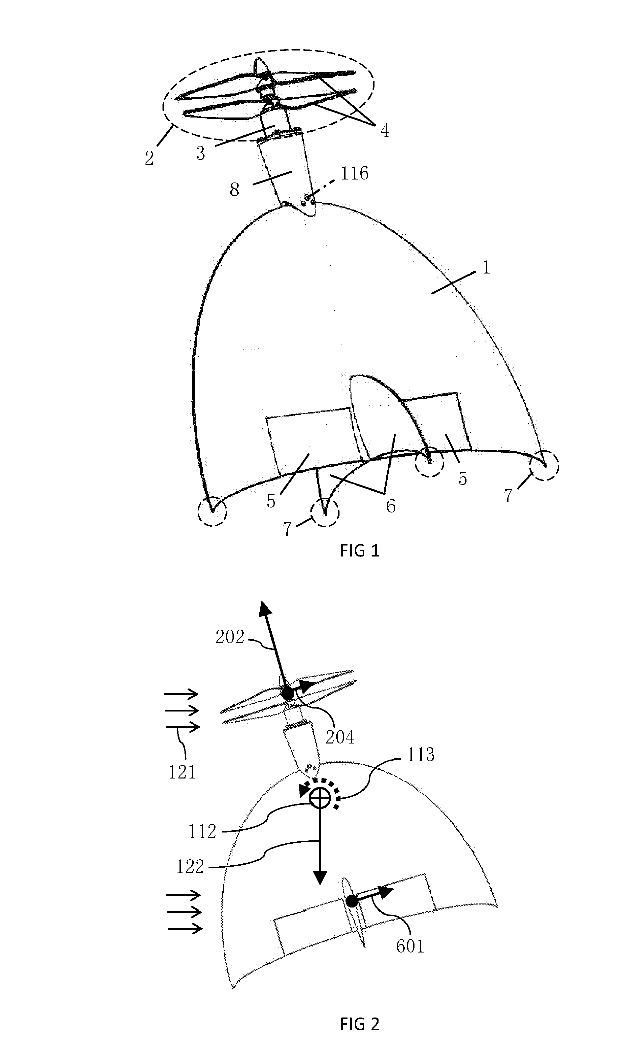
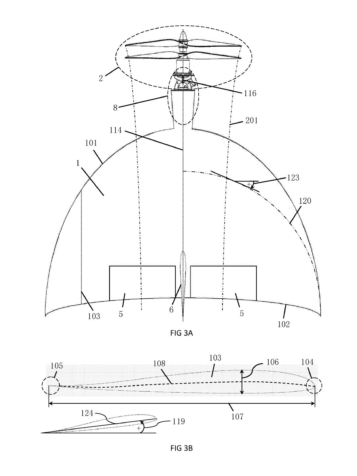
[0095]An example embodiment of the control system is provided with various features and parts, as described in BRIEF SUMMARY OF THE INVENTION. For Embodiment A, the mount (8) is a nacelle-like structure that protrudes forward from the root leading-edge of the fixed-wing (1), as seen in FIG. 1. When the mount (8) is in its neutral position, it lies on the plane of symmetry (114), and it may or may not be coaxial with the root chord-line of the fixed-wing (1). A preferred structure for the mount (8) is depicted in FIG. 14. It comprises: a plurality of frames (808), a plurality of ribs (809), a plurality of stringers (810), and skin (811) that can support loads, as seen in FIG. 16. The stringers (810) pass through corresponding holes cut into the ribs (809). Protrusions on the frames (808) pass through corresponding holes in the aftmost rib (809). The stringers (810), ribs (809), and frames (808) are joined together, preferably with adhesive. Skin (811) is placed around the ribs (809) ...

embodiment b

[0103]Another example of the control system is provided in Embodiment B, which follows from the discussion in BRIEF SUMMARY OF THE INVENTION. Embodiment B is depicted in FIG. 18. It can be used when Embodiment A is inappropriate to a given application. Rather than rotating about a pin (803) near the leading-edge of the wing (101) the hinge axis (116) is moved until it is nearly coincident with the thruster's (2) center-of-mass. As a result, high rotational accelerations about the hinge axis (116) can be achieved using a smaller and lighter-weight servo (804) that better-resists breaking during tip-overs and potential skid-landings. Yaw-jerking becomes negligible as reactionary moment about the fixed-wing (1) is minimized.

[0104]For Embodiment B the mount (8) comprises an aft mount (813) and a forward mount (817), as seen in FIG. 19. The aft mount (813) is fixed to the aircraft. The aft mount (813) comprises an aft mounting plate (832), which is located on a fixed-part of the aircraft...

embodiment b1

[0110]It is convenient to manufacture the mount (8) by cutting components out of a flat plate of material using a CNC machine. This allows materials with high strength-to-weight ratios to be used, including fiberglass and carbon fiber. Thin flat material oriented approximately parallel to a horizontal plane is not very resistant to bending from applied vertically-oriented forces. Therefore, supports (824) that lie within planes approximately perpendicular to the horizontal plane (115) may be included. The supports (824) can help the plates (814, 815, 818, 819) resist bending stresses, as seen in FIGS. 19-21. Supports (824) connect-to, or are integrated-with, a mount (813, 817) and its plates (814, 815, 818, 819).


PUM


Abstract

An unmanned aircraft capable of vertical takeoff, vertical landing, and / or flight in a hovering orientation is presented; its fixed-wing is positively-swept and of low aspect-ratio with suitable airfoils. The unmanned aircraft includes a thruster comprising two contra-rotating motors and propellers forward of the fixed-wing's leading-edge and a rudderless fin aft of the center-of-mass, all of which lie on the aircraft's plane-of-symmetry. Two elevons provide pitch and roll control. The unmanned aircraft can stand upright on its feet.A control system for aircraft with at least one wing is also presented. The control system includes a mount and attached thruster which lie on the plane-of-symmetry forward of the fixed-wing's leading-edge. A hinge axis approximately perpendicular to the aircraft's horizontal plane passes through the mount. The thruster rotates about the hinge axis for aircraft yaw control.

Description

CROSS-REFERENCE TO RELATED APPLICATIONS[0001]This application is claims priority to People's Republic of China Application (CN) 201810163609.9 with a filing date of Feb. 27, 2018 (2018-02-27).BACKGROUND OF THE INVENTION(1) Field of Invention[0002]The novel apparatus presented below relate to the field of control systems and aircraft.(2) Description of Related ArtAircraft[0003]Aircraft have many private and commercial applications as aerial sensor platforms (i.e. video-acquisition), delivery systems, environmental sensing, and communication relays. They can be classified based on their method of aerodynamic lift generation as: fixed-wing, rotary-wing, hybrid, or flapping-wing. Such vehicles are useful in various private and commercial applications, as well as public sectors, including: search and rescue, border security, law enforcement, and environmental monitoring.[0004]Traditional hover-capable fixed-wing model aircraft have been around for decades. They have a single propeller an...

Claims


Application Information

Patent Timeline
Patent Type & Authority Applications(United States)
IPC IPC(8): B64C27/22B64C39/02B64C29/02
CPCB64C27/22B64C29/02B64C39/024B64C9/00B64C11/00B64C2009/005B64U70/80B64U10/25B64U2201/00B64U30/20B64U50/13
Inventor RANDALL, RYAN M.CHEN, CHUNMEI
Owner QINGDAO RANDALL AERODYNAMICS ENG LLC
Why Eureka
Try Eureka