
System and method to percutaneously block painful sensations

Active Publication Date: 2019-09-19
AVENT INVESTMENT LLC
View PDF3 Cites 5 Cited by
  • Summary
  • Abstract
  • Description
  • Claims
  • Application Information

AI Technical Summary

Benefits of technology

This patent describes a system and method for blocking nerve conduction to treat pain through electrical stimulation. The procedure involves using a percutaneous lead with electrodes placed parallel to a nerve over an overlapping nerve region of at least 3 millimeters in size. The complete block of nerve conduction ensures that the patient does not feel any pain or discomfort. The method can be performed using standard percutaneous leads and an introducer for accurate positioning. The electrical stimulation intensity can be delivered for a time period ranging from about 1 to 6 weeks to treat and manage pain. The system can also provide a carry-over blocking effect, where the blocking of painful sensations hosted by the target nerve can extend for a time period extending up to about -1000% of the time period during which the desired stimulation intensity is delivered.

Problems solved by technology

Destructive methods, such as radiofrequency ablation, are treatments of last resort, and are typically not used for treating acute (i.e., post-surgical) pain.
Such high-frequency and conventional electrical stimulation treatment do not fully block nerve conduction as a means to treat pain.
Further, the usability of high-frequency electrical stimulation is challenged by “onset activity” and the “co-excitation” of nearby excitable tissues.
Onset response elicited in a peripheral nerve may lead to uncomfortable sensations (i.e., pain), or uncomfortable motor contractions.
However, the investigated techniques have been either impractical for clinical implementation or have not eliminated the onset response to high frequency electrical stimulation.
As a result, the targeted nerve which is in close proximity to electrode may be blocked, but the more distant excitable tissues (i.e., muscles, blood vessels) may be activated, potentially causing motor contraction and / or vasospasm.

Method used


Image

  • System and method to percutaneously block painful sensations
  • System and method to percutaneously block painful sensations
  • System and method to percutaneously block painful sensations

Examples


example system # 1

EXAMPLE SYSTEM #1

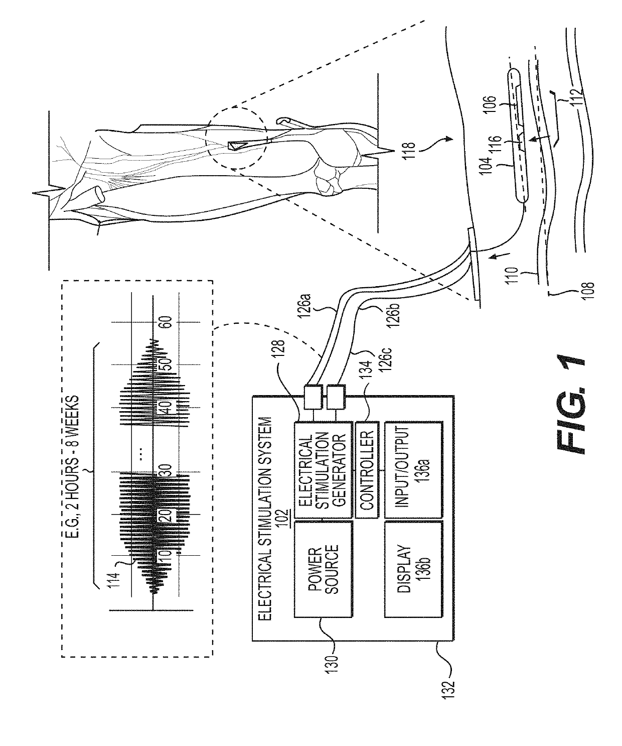
[0213]FIG. 1 is a diagram of an exemplary electrical stimulation system 102 configured to deliver electrical stimulation 114 from a percutaneous lead 104 comprising one or more percutaneous electrode(s) 106 placed in parallel, or substantially in parallel, and without direct contact, to a long axis 108 of a target nerve 110 over an overlapping nerve region 112 of greater than about 3 millimeters, to block nerve conduction through the overlapping nerve region 112, in accordance with an illustrative embodiment. This overlapping nerve region 112 is also referred to herein as a point of nerve conduction block 112. A percutaneous electrode 106 does not have to directly contact the nerve trunk, e.g., the epineurium, though it can, and the electrode and its associated assembly can be offset from the nerve trunk by up to 15 millimeters. The intensity or power of the electrical stimulation may be adjusted to compensate for individual patient perception of pain as well as for...

example system # 2

EXAMPLE SYSTEM #2

Implantable Stimulator

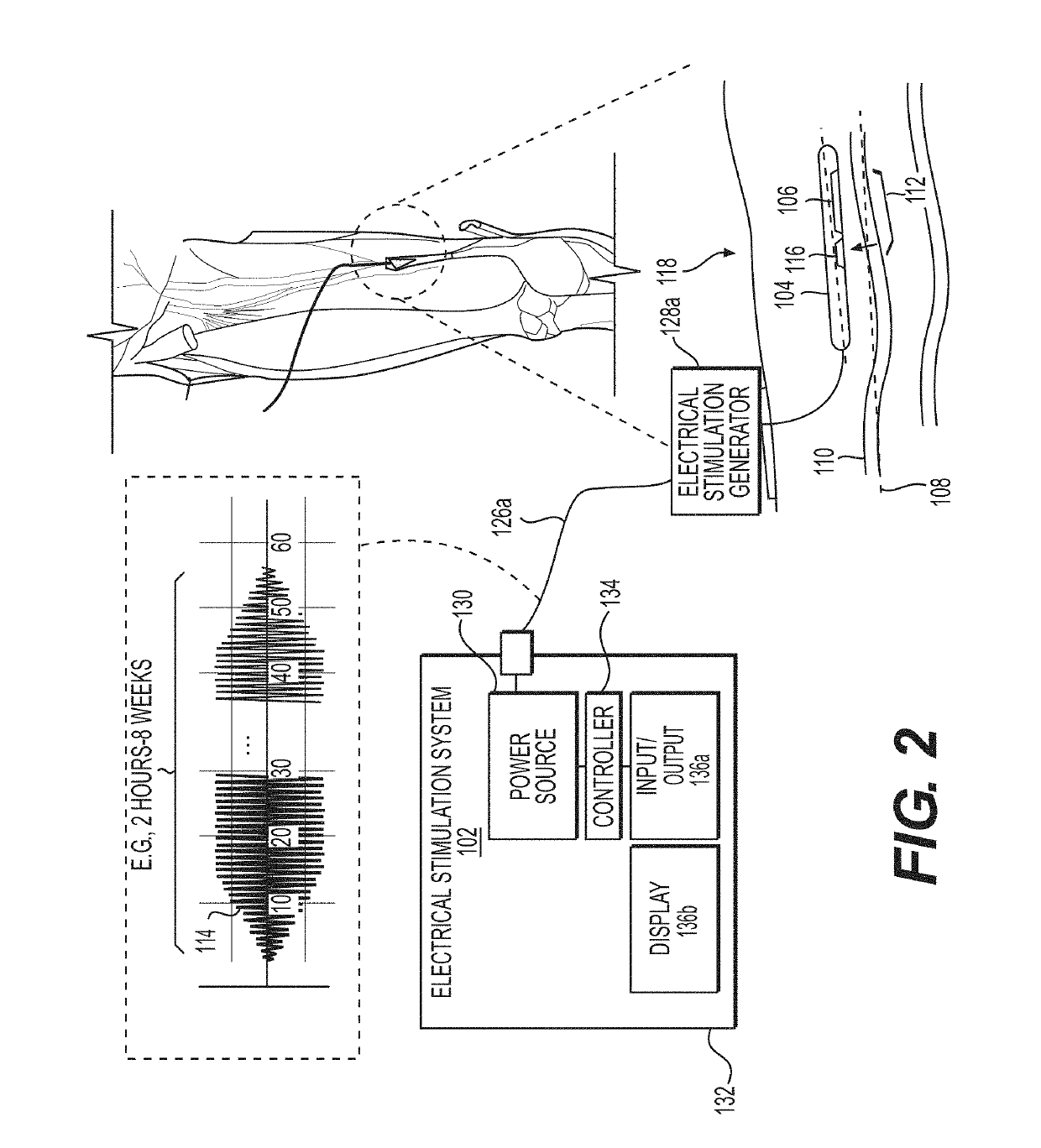
[0225]FIG. 2 is a diagram of another exemplary electrical stimulation system 102a configured to deliver electrical stimulation (114) from a percutaneous leads 104 comprising one or more percutaneous electrode(s) 106 placed in parallel, or substantially in parallel, and without direct contact, to a long axis 108 of a target nerve 110 over an overlapping nerve region 112 of greater than about 3 millimeters, to block nerve conduction through the overlapping nerve region 112, in accordance with an illustrative embodiment.

[0226]Rather than an external electrical stimulator 128, the electrical stimulation system 102a includes an implantable stimulator 128a that can be placed on, or under, the skin of the patient 118.

[0227]Method of Treatment by Placement of Percutaneous Electrode in Parallel Orientation to a Target Nerve

[0228]In another aspect, a method of treatment is provided to place a percutaneous lead at a treatment site of a subject to block ne...

example # 1

EXAMPLE #1

[0397]FIG. 27 demonstrates the sensory response in an able-bodied subject to a percutaneously delivered high-frequency electrical stimulation. The sensations are consistent with the onset response elicited by high-frequency stimulation of a sensory nerve. An S8 (Abbott) electrode was used to stimulate the saphenous nerve at a site 5-to-10 cm proximal to the ankle. The stimulation consisted of a constant-current, 10 kHz sinusoidal waveform, and it was delivered for a period of 20 seconds at various amplitudes, including 4 mA (A—see reference number 2704), 6 mA (B—see reference number 2706), 10 mA (C—see reference number 2708), and 15 mA (D—see reference number 2710). The subject verbally described the quality of the evoked sensations (e.g. light-touch or pain) and indicated the intensity of the sensation on an 11-point scale: levels 1 and 2 defined tactile sensation, level 3 defined the pain threshold, and levels 4-10 indicated a mild-to-severe painful sensation.

[0398]FIG. ...


PUM


Abstract

The exemplified systems and methods facilitate a nerve conduction block at a target nerve using electrical stimulation applied from one or more electrodes located on a percutaneous lead that are placed in parallel, or substantially in parallel, and without direct contact, to a long axis of the peripheral nerve over an overlapping nerve region of greater than about 3 millimeters. The exemplified system and method can be further configured to block nerve condition without eliciting onset activity and co-excitation of non-targeted structures. The exemplified method and system can be performed using conventional percutaneous leads, though an improved percutaneous lead design is disclosed herein. In an aspect, an introducer is disclosed that facilitates accurate and consistent insertion of the percutaneous lead to the specified or intended position relative to the target nerve. In another aspect, a treatment kit comprising the various system components to treat pain is disclosed.

Description

RELATED APPLICATION[0001]This application claims priority to, and the benefit of, U.S. Provisional Application No. 62 / 643,216, filed Mar. 15, 2018, titled “System and Method to Percutaneously Block Painful Sensations Elicited by a Peripheral Nerve Without Eliciting Non-Targeted Motor and Sensor Activity,” which is incorporated by referenced herein in its entirety.FIELD OF THE INVENTION[0002]The disclosure relates generally to a system and method to block nerve fiber activity, e.g., to treat pain, particularly, to block peripheral nerve activity through electrical stimulation of a lead, e.g., a percutaneous lead.BACKGROUND OF THE INVENTION[0003]Pain can be treated by destructive and non-destructive methods that interfere with the transmission of pain signals sent to the brain. Destructive methods, such as radiofrequency ablation, are treatments of last resort, and are typically not used for treating acute (i.e., post-surgical) pain. Non-destructive methods to treat pain include the u...

Claims


Application Information

Patent Timeline
IPC IPC(8): A61N1/36A61N1/06A61N1/20
CPCA61N1/06A61N1/20A61N1/36017A61N1/36034A61N1/36021A61N1/0551A61N1/0553A61N1/0556A61N1/36057A61N1/36071A61N1/36128A61N1/0502A61B17/3468A61N1/05
Inventor SCHEPIS, ERIC A.SCHORR, PHILLIP A.SASTRY, SHYAMY R.CALDWELL, RYANPAGE, DAVID M.SOIN, AMOL
Owner AVENT INVESTMENT LLC
Learn More