
Mechanical Gauge for Estimating Inductance Changes in Resonant Power Transfer Systems With Flexible Coils for Use With Implanted Medical Devices

a technology of resonant power transfer system and mechanical gauge, which is applied in the field of medical devices, can solve the problems of increasing the difficulty of patients and providers, affecting the comfort of patients, and the weak heart of people with heart failure, so as to improve the comfort of patients and improve the wireless charging of implantable medical devices

Active Publication Date: 2019-09-26
TC1 LLC
View PDF5 Cites 4 Cited by
  • Summary
  • Abstract
  • Description
  • Claims
  • Application Information

AI Technical Summary

Benefits of technology

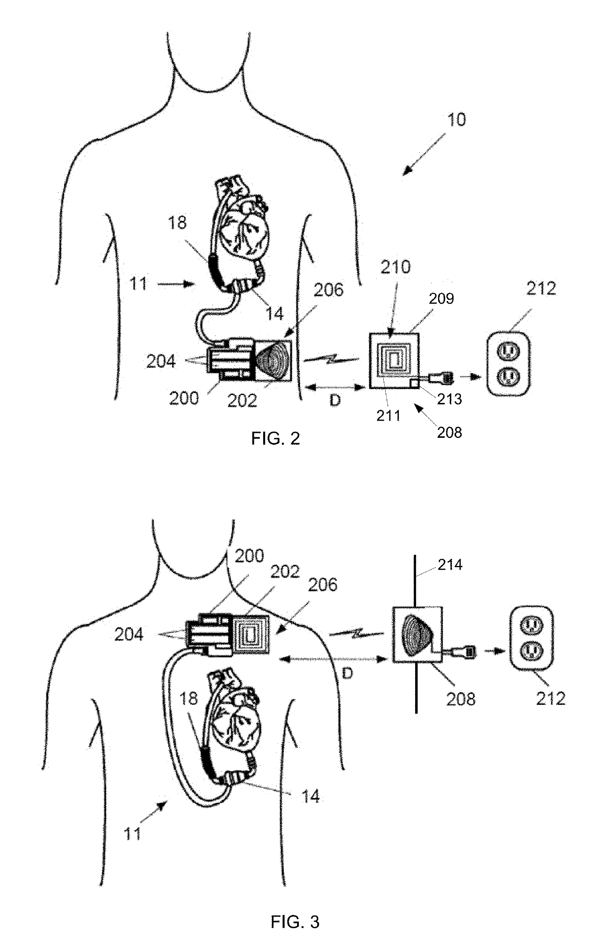
This patent provides better systems, methods, and devices for wireless charging of implantable medical devices such as ventricular assist devices. The systems include a charging device with a primary coil and an implantable medical device with a secondary coil that can be deformed to match patient anatomy and improve comfort. By monitoring changes in the ability of the coil to send and receive power, the processor can adjust the driving of the coil to match its resonant frequency, improving power transfer efficiency and reducing heat generation for patient safety and comfort.

Problems solved by technology

Whether power is provided via a wire or wirelessly, the providing of power to the implanted medical device creates many challenges for patients and providers.
People with heart failure often have shortness of breath and fatigue.
Years of living with blocked arteries or high blood pressure can leave your heart too weak to pump enough blood to your body.
As symptoms worsen, advanced heart failure develops.
While a VAD can greatly improve a patient's life, use of a VAD can provide challenges to the patient and provider.
These challenges can include the powering of the VAD.

Method used


Image

  • Mechanical Gauge for Estimating Inductance Changes in Resonant Power Transfer Systems With Flexible Coils for Use With Implanted Medical Devices
  • Mechanical Gauge for Estimating Inductance Changes in Resonant Power Transfer Systems With Flexible Coils for Use With Implanted Medical Devices
  • Mechanical Gauge for Estimating Inductance Changes in Resonant Power Transfer Systems With Flexible Coils for Use With Implanted Medical Devices

Examples


Embodiment Construction

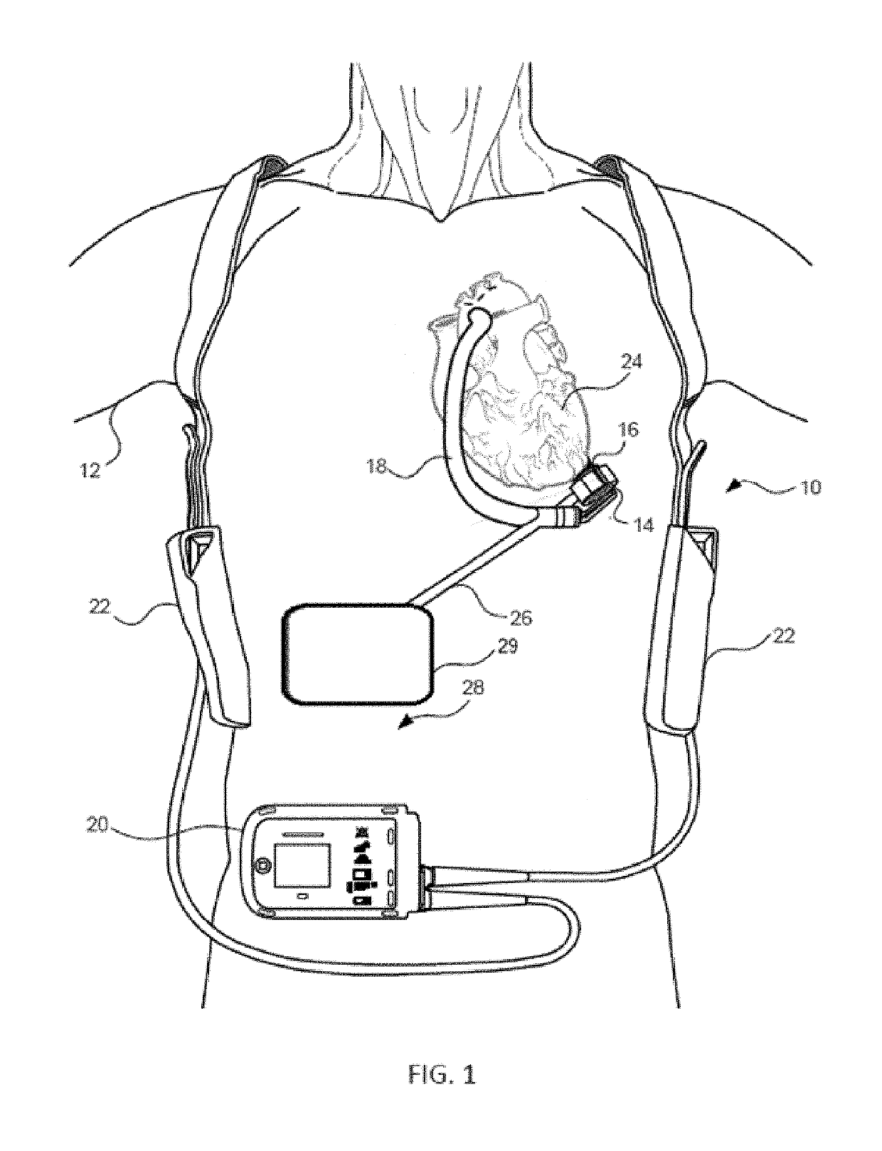
[0034]In implantable medical devices that utilize electrical power to enable their operation, power can provided through the use of a cord that extends through the skin to physically connect the implantable medical device to an external power source or alternatively through the use of features that allow wireless charging of the implantable medical device.

[0035]These problems from external powering of the implantable medical devices are particularly apparent in medical devices consuming relatively large amounts of power. For example, an implantable blood pump such as a VAD may use significantly more power than, for example, a pacemaker. Such implantable medical devices that consume large amounts of power can be constantly charged by an external charger that may be held proximate to a portion of a patient's body and / or be charged for significant periods of time by the external charger being held proximate to the portion of the patient's body. This continuous or extended use of the ex...


PUM


Abstract

Systems and devices for improving wireless power transmission are disclosed herein. The system can include an implantable medical device that can include an energy storage component and a secondary coil electrically coupled to the energy storage component. The system can include a charging device. The charging device can include a flexible housing defining an internal volume, a resonant circuit, a plurality of sensors coupled to the primary coil, and processor. The resonant circuit can include a deformable primary coil located within the internal volume of the housing. The processor can determine a deformation of the primary coil based on at least one signal received from at least one of the plurality of sensors.

Description

CROSS REFERENCE TO RELATED APPLICATIONS[0001]The present application claims the benefit under 35 USC § 119(e) of U.S. Provisional Appln. No. 62 / 645,594 filed Mar. 20, 2018; the full disclosure which is incorporated herein by reference in its entirety for all purposes.BACKGROUND[0002]This application relates generally to medical devices, and more specifically relates to methods and devices for improved charging of wireless medical devices.[0003]Implanted medical devices frequently utilize electrical power to enable their operation. This electrical power is frequently provided through the use of a driveline that extends through the skin to physically connect the Implanted medical device to an external power source or alternatively through the use of features that allow wireless charging of the Implanted medical device. Whether power is provided via a wire or wirelessly, the providing of power to the implanted medical device creates many challenges for patients and providers.[0004]One ...

Claims


Application Information

Patent Timeline
Patent Type & Authority Applications(United States)
IPC IPC(8): A61M1/12
CPCA61M1/1086H02J50/12H02J7/025A61N1/3787A61M1/127A61M1/122A61N1/3627A61M2205/82A61M2205/8243H02J50/80A61M60/816A61M60/232A61M60/419A61M60/237A61M60/178A61M60/538A61M60/875H02J2310/23H04B5/26H04B5/72H04B5/79H02J7/00A61M60/148
Inventor HANSEN, JOHN FREDDY
Owner TC1 LLC
Learn More