Composition Suitable for Application with Laser Induced Forward Transfer (LIFT)

a technology of forward transfer and laser, applied in the direction of application, ink, vacuum evaporation coating, etc., can solve the problems of affecting the process speed, the volume and/or dot size of the currently used dispense technology, and the challenge of downsizing components such as microelectromechanical systems (mems)

Inactive Publication Date: 2019-10-03
HENKEL KGAA
View PDF0 Cites 2 Cited by
  • Summary
  • Abstract
  • Description
  • Claims
  • Application Information

AI Technical Summary

Benefits of technology

[0013]The present invention relates to a composition comprising a) one or more resin; b) electrically conductive particles and / or non-conductive particles and / or thermally conductive particles; and c) from 5 to 40% of a solvent and / or a reactive diluent by weight of the total weight of the composition, wherein said solvent and / or reactive diluent has a boiling point higher than 130° C., and wherein said composition has no crossing over of the storage modulus (G′) and the loss modulus (G″), and wherein the storage modulus (G′) is lower than the loss modulus (G″).

Problems solved by technology

The downsizing of components like microelectromechanical systems (MEMS) is challenging for the industry standard application technologies like dispensing, printing, jetting or pin transfer.
Currently used dispense technologies have all reached their limits in regards volume and / or dot size and the required process speed.
Needle dispensing and pin transfer both can go down till 75 μm on dot size, however, the process speed will be negatively impacted, and therefore, a very accurate and expensive robot system is required.
Printing, on the other hand, is a very fast technique, however, the resolution is low and only large dots can be produced.
With dispensing, smaller dot sizes can be produced with reasonably high resolution, however, this technique is slower and less reproducible compared to printing.
Typically, LIFT cannot be used to deposit complex crystalline, multi-component materials as they tend to decompose when vaporized and may become amorphous upon condensation.
Moreover, because the material to be transferred is vaporized, it becomes more reactive and can more easily become degraded, oxidized, or contaminated.
Generally the LIFT is not well suited for the transfer of organic materials, since many organic materials are fragile, thermally labile, and can be irreversibly damaged during deposition.
Furthermore, functional groups on an organic polymer may be irreversibly damaged by direct exposure to laser energy.
It is well known that adhesives can be made suitable for screen printing, jetting, pin transfer and dispensing, however this has not been equally straightforward process for the LIFT process.

Method used


Image

  • Composition Suitable for Application with Laser Induced Forward Transfer (LIFT)
  • Composition Suitable for Application with Laser Induced Forward Transfer (LIFT)
  • Composition Suitable for Application with Laser Induced Forward Transfer (LIFT)

Examples


example 1

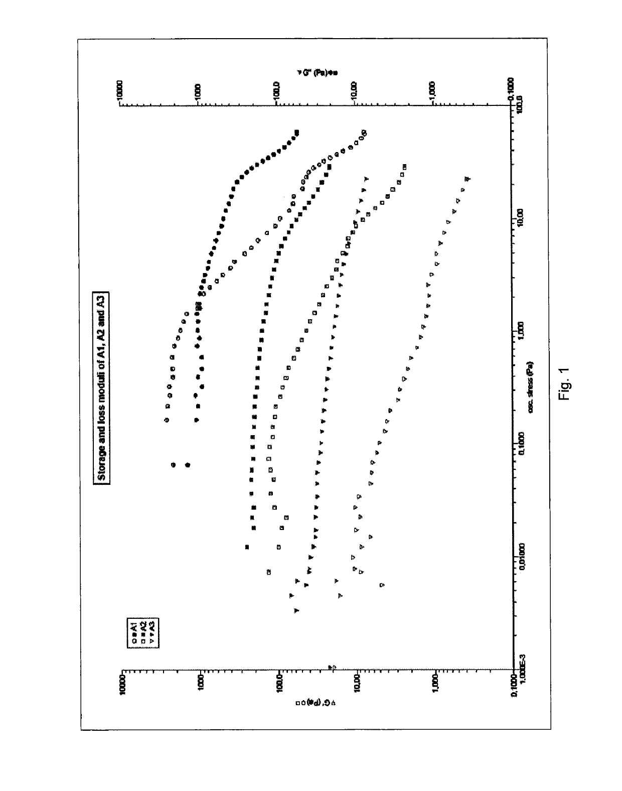
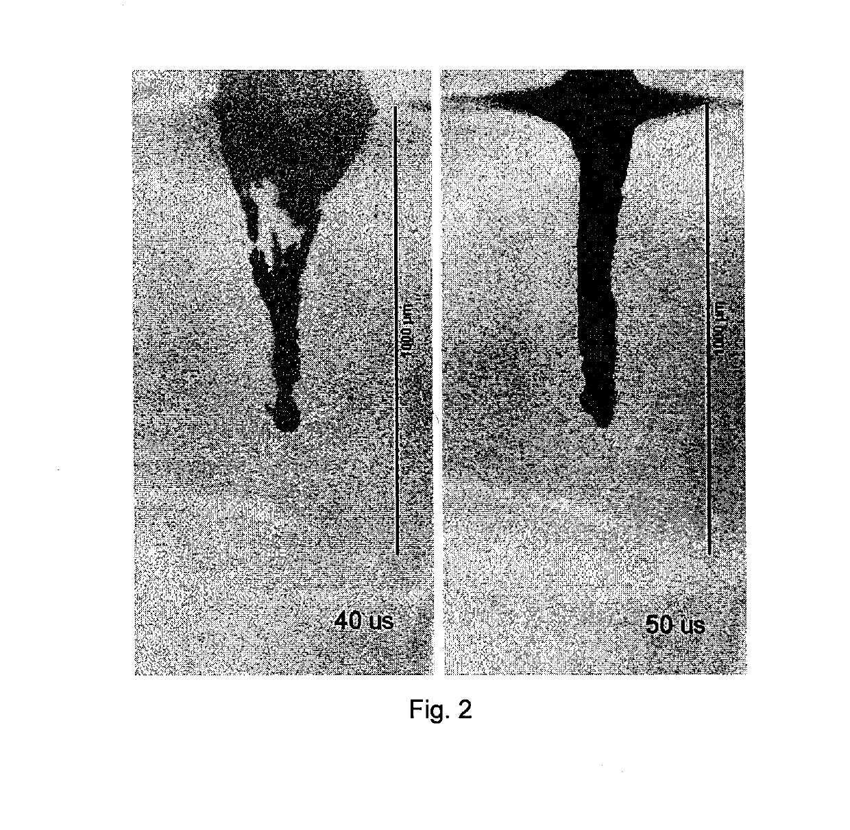
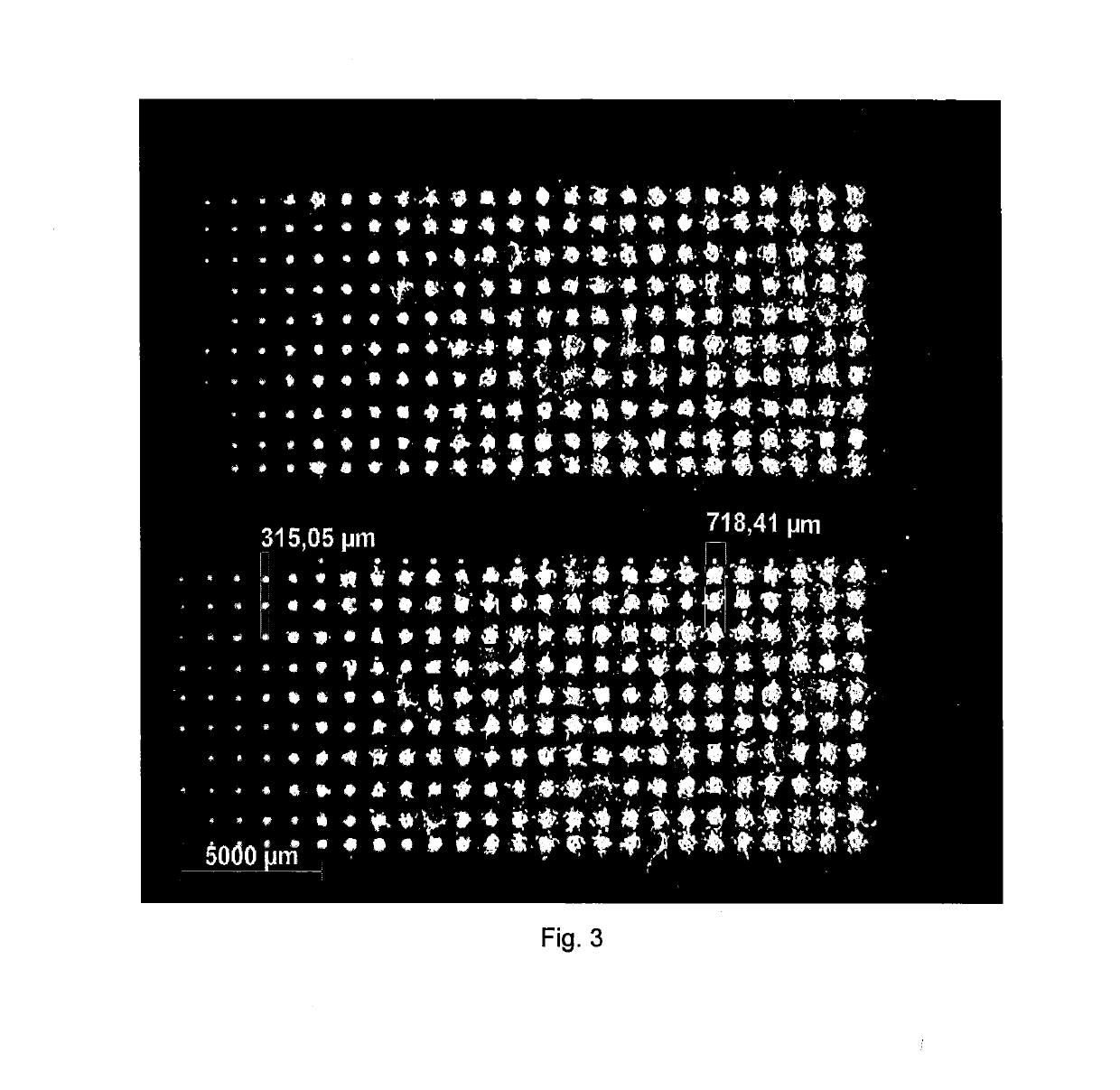
[0062]Composition A3 and composition B had a differed viscosity. Detailed compositions are listed in the table 1. The viscosity of composition B was lowered by addition of an organic solvent. Testing showed that the composition B was not applicable with LIFT (illustrated in FIG. 3), whereas lower viscosity composition A3 was applicable with LIFT. FIG. 4 illustrates this effect. Explosion of a material was observed during LIFT process as can be seen on the left side of the FIG. 4 when the composition having a high viscosity (composition B) was used in LIFT process. A jet was formed, as can be seen on the right side of the FIG. 4, for the composition having a suitable viscosity (composition A3).

TABLE 1CompositionCompositionComponentA3BLinear bifunctional epoxy8.068.06Bis F epoxy12.1012.10Seikacure S (amine hardener)2.522.52Micron sized silver flake77.1277.12Epoxy silane compound0.200.20Organic solvent bp. (213-218° C.)15.000.00Viscosity (Pas)1.011.1Crossover of G′ and G″NoYesApplicabl...

example 2

[0063]Composition C and composition D had a differed reactive diluent used in the composition, more specifically, boiling point of the reactive diluent was different. Detailed compositions are listed in table 2. Testing showed that the composition C was not applicable with LIFT, whereas composition D was applicable with LIFT. FIG. 5 illustrates this effect. Explosion of the material was observed during LIFT process using the composition comprising low boiling point reactive diluent (composition C), as can be seen on the left side of the FIG. 5. Whereas, the composition comprising a high boiling point reactive diluent (composition D), a jet was formed as can be seen on the right side of the FIG. 5.

TABLE 2CompositionCompositionComponentCDLinear bifunctional epoxy8.068.06Bis F epoxy12.1012.10Seikacure S (amine hardener)2.522.52Micron sized silver flake77.1277.12Epoxy silane compound0.200.20Epoxy diluent 1 (BP 124° C.)8.000.00Epoxy diluent 2 (BP > 250° C.)0.008.00Viscosity (Pas)1.92.0Cr...

example 3

[0064]Composition A1 and composition E had a differed quantity of the solvent used in the composition. Detailed compositions are listed in table 3. Testing showed that the composition A1 was not applicable with LIFT, whereas composition E was applicable with LIFT. FIG. 6 illustrates this effect. Explosion of the material was observed during LIFT process using the composition comprising lower quantity of the solvent (composition A1), as can be seen on the left side of the FIG. 6. Whereas, the composition comprising a higher quantity of the solvent (composition E), a jet was formed as can be seen on the right side of the FIG. 6.

TABLE 3CompositionCompositionComponentA1ELinear bifunctional epoxy8.068.06Bis F epoxy12.1012.10Seikacure S (amine hardener)2.522.52Micron sized silver flake77.1277.12Epoxy silane compound0.200.20Organic solvent bp. (213-218° C.)2.008.00Viscosity (Pas)7.02.6Crossover of G′ and G″YesNoApplicable with LIFTNoYes


PUM

PropertyMeasurementUnit
boiling pointaaaaaaaaaa
sizeaaaaaaaaaa

Abstract

The present invention relates to a composition comprising a) one or more resin; b) electrically conductive particles and/or non-conductive particles and/or thermally conductive particles; and c) from 5 to 40% of a solvent and/or a reactive diluent by weight of the total weight of the composition, wherein said solvent and/or reactive diluent has a boiling point higher than 130° C., and wherein said composition has no crossing over of the storage modulus (G′) and the loss modulus (G″), and wherein the storage modulus (G′) is lower than the loss modulus (G″). A composition according to the present invention is suitable for application with laser Induced Forward Transfer (LIFT).

Description

TECHNICAL FIELD OF THE INVENTION[0001]The present invention relates to a composition suitable for application with Laser Induced Forward Transfer (LIFT).BACKGROUND OF THE INVENTION[0002]The downsizing of components like microelectromechanical systems (MEMS) is challenging for the industry standard application technologies like dispensing, printing, jetting or pin transfer. Currently used dispense technologies have all reached their limits in regards volume and / or dot size and the required process speed. The limit in dot size for jetting technology is around 200 μm for standard materials used in the industry. Needle dispensing and pin transfer both can go down till 75 μm on dot size, however, the process speed will be negatively impacted, and therefore, a very accurate and expensive robot system is required. Printing, on the other hand, is a very fast technique, however, the resolution is low and only large dots can be produced. With dispensing, smaller dot sizes can be produced with...

Claims


Application Information

Patent Timeline
Patent Type & Authority Applications(United States)
IPC IPC(8): C23C14/12C08K3/08C23C14/28
CPCC08K2003/0806C08K2201/001C23C14/12C23C14/28C08K3/08C09D11/10C09D11/52H01L21/2855C08K3/013C23C14/3485C08K3/10
Inventor VAN DER MEULEN, INGEDREEZEN, GUNTHERWIJGAERTS, JANARUTINOV, GARIGIESBERS, MERIJN
Owner HENKEL KGAA
Why Eureka
Try Eureka