Wide tuning range, frequency agile MIMO antenna for cognitive radio front ends

Active Publication Date: 2019-10-03
KING FAHD UNIVERSITY OF PETROLEUM AND MINERALS
View PDF0 Cites 0 Cited by
  • Summary
  • Abstract
  • Description
  • Claims
  • Application Information

AI Technical Summary

Benefits of technology

[0014]The present invention is a compact, frequency-agile, MIMO antenna for CR platforms for cellular communication front ends, wherein the antenna has a wide tuning range covering several well-known wireless standards and enables switching between operating bands in CR platforms.
[0015]Slot

Problems solved by technology

The increasing demand of wireless services has made the radio spectrum a very scarce and precious resource.
Most current wireless network

Method used


Image

  • Wide tuning range, frequency agile MIMO antenna for cognitive radio front ends
  • Wide tuning range, frequency agile MIMO antenna for cognitive radio front ends
  • Wide tuning range, frequency agile MIMO antenna for cognitive radio front ends

Examples


Embodiment Construction

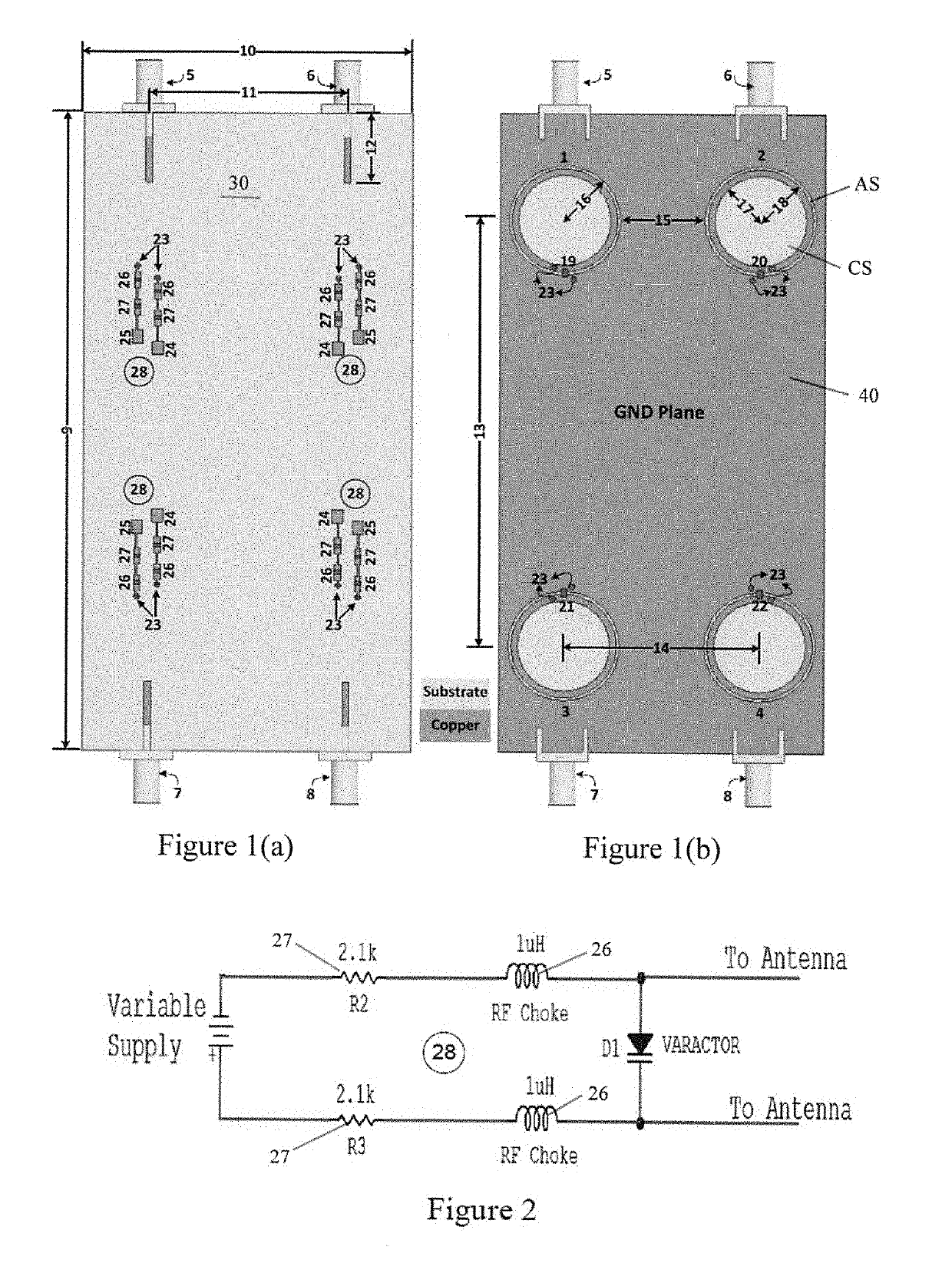
[0029]The geometry of the proposed 4-element, slot-based MIMO antenna system is shown in FIGS. 1(a) and 1(b), with FIG. 1(a) showing the top layer and FIG. 1(b) showing the bottom layer. The antenna is designed on a Rogers RO4350 substrate with a relative permittivity (εr) of 3.48, loss tangent of 0.0036 and a board thickness of 0.76 mm. All antenna elements of a single design are similar in structure.

[0030]As seen best in FIG. 1(a), the top layer 30 of the antenna system contains a microstrip feed-line 12 and varactor diode biasing circuitry 28 for each diode. Reconfigurability is achieved by using the varactor diodes to tune the resonance frequency over a wide operation band. The complete biasing circuit schematic 28 for a varactor diode for a single antenna element is shown in FIG. 2. The board used in the top layer in the particular example disclosed herein has a length dimension 9 of 120 mm and a width dimensions 10 of 60 mm.

[0031]The bottom layer 40 contains four annular slot,...


PUM


Abstract

A low profile, 4-element, slot-based, frequency reconfigurable MIMO antenna for cognitive radio (CR) platforms for cellular communication front ends. The antenna is on a board having a top layer substrate and a bottom layer ground plane. The bottom layer ground plane contains four antenna elements, each antenna element having a circular slot and an annular slot spaced outwardly from and extending circumferentially around the circular slot. The bottom layer contains a microstrip feed-line for each antenna element. Varactor diodes on the top layer span the width of each annular slot to tune the resonance frequency over a wide operation band. The antenna covers a wide frequency band from 1800 MHz to 2450 MHz and supports several well-known wireless standards bands, including GSM1800, LTE, UMTS and WLAN, as well as many others.

Description

FIELD OF THE INVENTION[0001]This invention relates generally to the field of wide-band wireless communication systems and consumer electronic devices. More particularly, it relates to reconfigurable multiple-input-multiple-output (MIMO) antenna systems for cognitive radio (CR) platforms for compact wireless devices and LTE mobile handsets. The complete antenna setup can be used in radio frequency based applications, including 4G cellular systems.BACKGROUND OF THE INVENTION[0002]New trends in modern communication systems have emerged as a result of the growing data rate requirements for modern wireless systems and the need for multi-standard operation in smart wireless devices. The increasing demand of wireless services has made the radio spectrum a very scarce and precious resource. Most current wireless networks characterized by fixed spectrum assignment policies are inefficient, with only 15% to 85% of the licensed spectrum utilized on average.[0003]To meet the high data rate requ...

Claims


Application Information

Patent Timeline
IPC IPC(8): H01Q5/10H01Q13/10H01Q5/50H01Q21/00
CPCH01Q21/00H01Q5/10H01Q1/38H01Q13/10H01Q5/50H01Q1/243H01Q5/321H01Q13/106H01Q21/28
Inventor HUSSAIN, RIFAQATSHARAWI, MOHAMMAD S
Owner KING FAHD UNIVERSITY OF PETROLEUM AND MINERALS
Why Eureka
Try Eureka