Trap assembly and system for trapping polymer vapors in process oven vacuum systems

a vacuum system and polymer vapor technology, applied in the field of vacuum systems, can solve the problems of continuous shrinkage of feature sizes, shrinkage of integrated circuit design rules that has simultaneously reduced wiring pitch, and signal propagation delay in the interconnection an appreciable fraction of the total cycle tim

Inactive Publication Date: 2019-10-17
YIELD ENG SYST INC
View PDF0 Cites 4 Cited by
  • Summary
  • Abstract
  • Description
  • Claims
  • Application Information

AI Technical Summary

Problems solved by technology

Such ultralarge scale integration has resulted in a continued shrinkage of feature sizes with the result that a large number of devices are made available on a single chip.
The shrinkage in integrated circuit design rules has simultaneously reduced the wiring pitch.
These have made the signal propagation delay in the interconnects an appreciable fraction of the total cycle time.
Unfortunately, polyimide typically requires a long time to cure when conventional heating techniques are used.
In addition, there are other problems involved with curing polyimide resin with conventional heat.
This can cause various physical defects, such as the formation of voids, and can result in inferior mechanical properties such as reduced modulus, enhanced swelling, solvent uptake, and coefficient of thermal expansion.
Each of these items sought to be eliminated may interfere with subsequent process steps, or enhance the probability of failure of a device containing the polyimide layer.
The vacuum lines run the risk of having vaporized liquids condensing along their interiors, resulting in coatings within these lines.
This may result in the need to replace these lines periodically, which may present quite a maintenance burden upon operators of such process ovens.
This approach may still result in significant condensation within vacuum lines in the system.
The risk having vaporized liquids condensing in inappropriate locations within a system is compounded with processes which result in even larger quantities of vaporized liquid being released.
The larger surface areas may release significant amounts of vapor, which in turn may condense along exhaust lines, or in other inappropriate locations, which may then often require cleaning or replacement of system components.
In some applications, the liberated compounds may be so voluminous that the vacuum pump may become blocked or otherwise have its operation impacted.
Further, the larger volume of liberated compounds which may result from FOWLP and / or panel level wafer processing may present an environmental concern, such that it may be advisable, or required, to remove the material within the chamber exhaust.

Method used


Image

  • Trap assembly and system for trapping polymer vapors in process oven vacuum systems
  • Trap assembly and system for trapping polymer vapors in process oven vacuum systems
  • Trap assembly and system for trapping polymer vapors in process oven vacuum systems

Examples


second embodiment

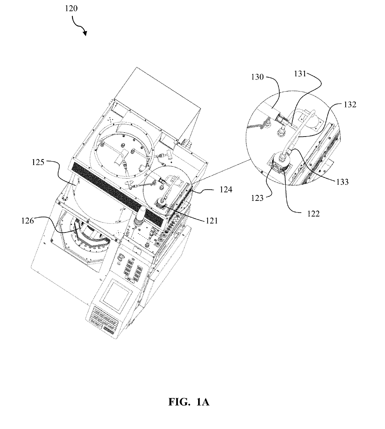
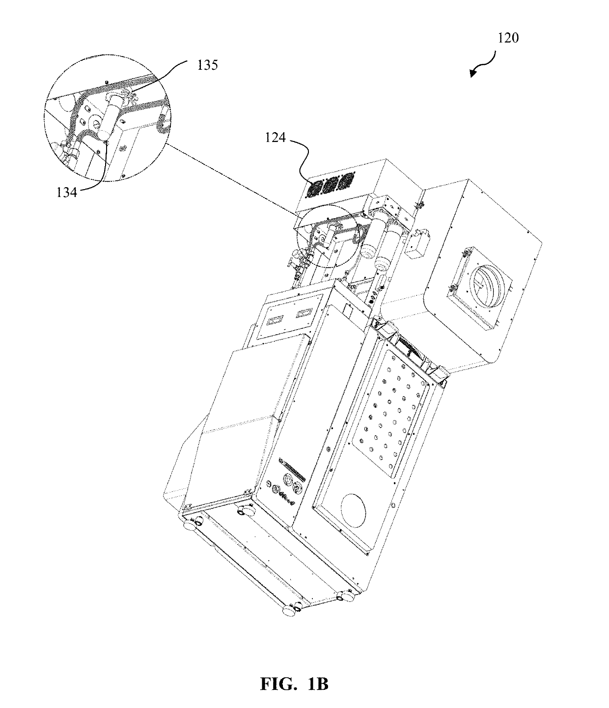
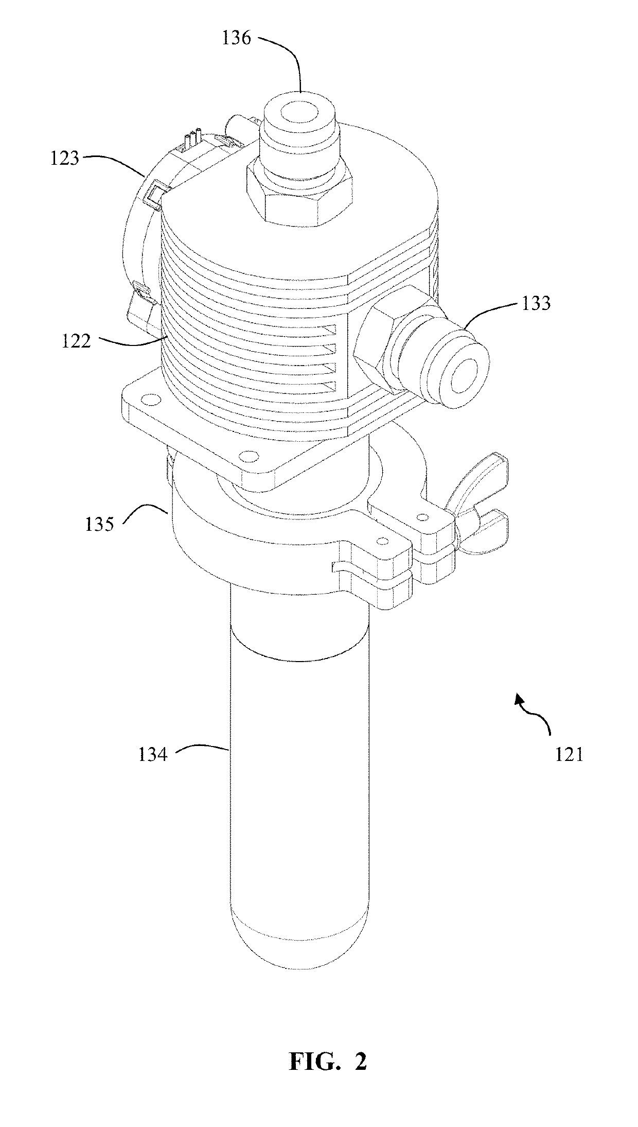
[0046]Referring to the cross-sectional view of the trap assembly 221 seen in FIG. 16, the chamber exhaust flow 270 enters the trap assembly via the trap inlet 233. The chamber exhaust flow may be routed to the trap inlet 233 via heated lines adapted to minimize or prevent condensation of vapors prior to their arrival at the trap assembly. The chamber exhaust flow 270 enters the condensation chamber within the condensing body. The inside surface 251 of the condensing body, which is also the outside perimeter of the condensation chamber, is cooled as described above. In this embodiment, the chamber exhaust flow 270 may enter the condensing body 222 and is deflected around the flow deflector 240. The chamber exhaust flow 270 flows along the interior surface 251 as it routes around the flow deflector 240. The flow may then enter the orifice 243 into the center portion of the flow deflector and up to the trap outlet 236. The cooled inside surface 251 leads to condensation of the vapors w...

first embodiment

[0047]FIG. 19 illustrates a flow deflector 240 according to the present invention. The flow deflector 240 is cylindrical and has a principal axis which is vertical. A mounting flange 244 allows for coupling to the condenser body. An orifice 243 is seen along the side of the flow deflector 240. An opening 242 is seen at the bottom of the cylindrical flow deflector 240.

[0048]FIG. 20 illustrates a flow deflector 250 according to a second embodiment of the present invention. The flow deflector 250 is cylindrical and has a principal axis which is vertical. A mounting flange 254 allows for coupling to the condenser body. An orifice 253 is seen along the side of the flow deflector 250. An opening 252 is seen at the bottom of the cylindrical flow deflector 250 below a narrowing portion 251. In some aspects, the flow deflector may be of a conical profile.

[0049]In some embodiments of the present invention, a drying process is carried out in a process chamber with low pressure / vacuum capabilit...


PUM

PropertyMeasurementUnit
pressureaaaaaaaaaa
thicknessaaaaaaaaaa
pressureaaaaaaaaaa

Abstract

A trap system adapted to trap polyimide or other vapors exiting from a process chamber. The vapors are routed from the process chamber through a heated exit line at low pressure and then cooled, resulting in condensation at a selected location. The condensed vapors accumulate in a liquid trap. A method of condensing polymer vapors in vacuum exit lines of process chambers, where the flow which may have vaporized polymer vapor is cooled to enhance condensation at a chosen location. The liquid trap can be emptied and replaced, resulting in the removal of the condensed liquid. The chamber exit lines are protected from condensation build up.

Description

CROSS-REFERENCE TO RELATED APPLICATIONS[0001]This application is a continuation-in-part of U.S. patent application Ser. No. 15 / 812,753 to Moffat et al., filed Nov. 14, 2017, which claims priority to U.S. Provisional Patent Application No. 62 / 421,671 to Moffat et al., filed Nov. 14, 2017, both of which are hereby incorporated by reference in their entirety.FIELD OF THE INVENTION[0002]This invention relates to vacuum systems, namely a system for trapping condensation in a designated location outside of a process oven.BACKGROUND OF THE INVENTION[0003]A continuing trend in semiconductor technology is the formation of integrated circuit (IC) chips having more and faster circuits thereon. Such ultralarge scale integration has resulted in a continued shrinkage of feature sizes with the result that a large number of devices are made available on a single chip. With a limited chip surface area, the interconnect density typically expands above the substrate in a multi-level arrangement and th...

Claims


Application Information

Patent Timeline
Patent Type & Authority Applications(United States)
IPC IPC(8): B01D5/00
CPCB01D5/009B01D2221/14F04B37/14B01D2258/02B01D5/0045B01D5/006
Inventor MOFFAT, WILLIAMMCCOY, CRAIG WALTER
Owner YIELD ENG SYST INC
Why Eureka
Try Eureka