Improved system with an inflatable member for being arranged in the patient's respiratory tract

a technology of respiratory tract and inflatable member, which is applied in the field of systems with inflatable members, can solve the problems of tracheal damage, large increase in pressure within the inflatable member, and potential tissue damage to the trachea, and achieve the effect of safe evaluation of an organ

Active Publication Date: 2019-10-24
STROKE2PREVENT
View PDF0 Cites 2 Cited by
  • Summary
  • Abstract
  • Description
  • Claims
  • Application Information

AI Technical Summary

Benefits of technology

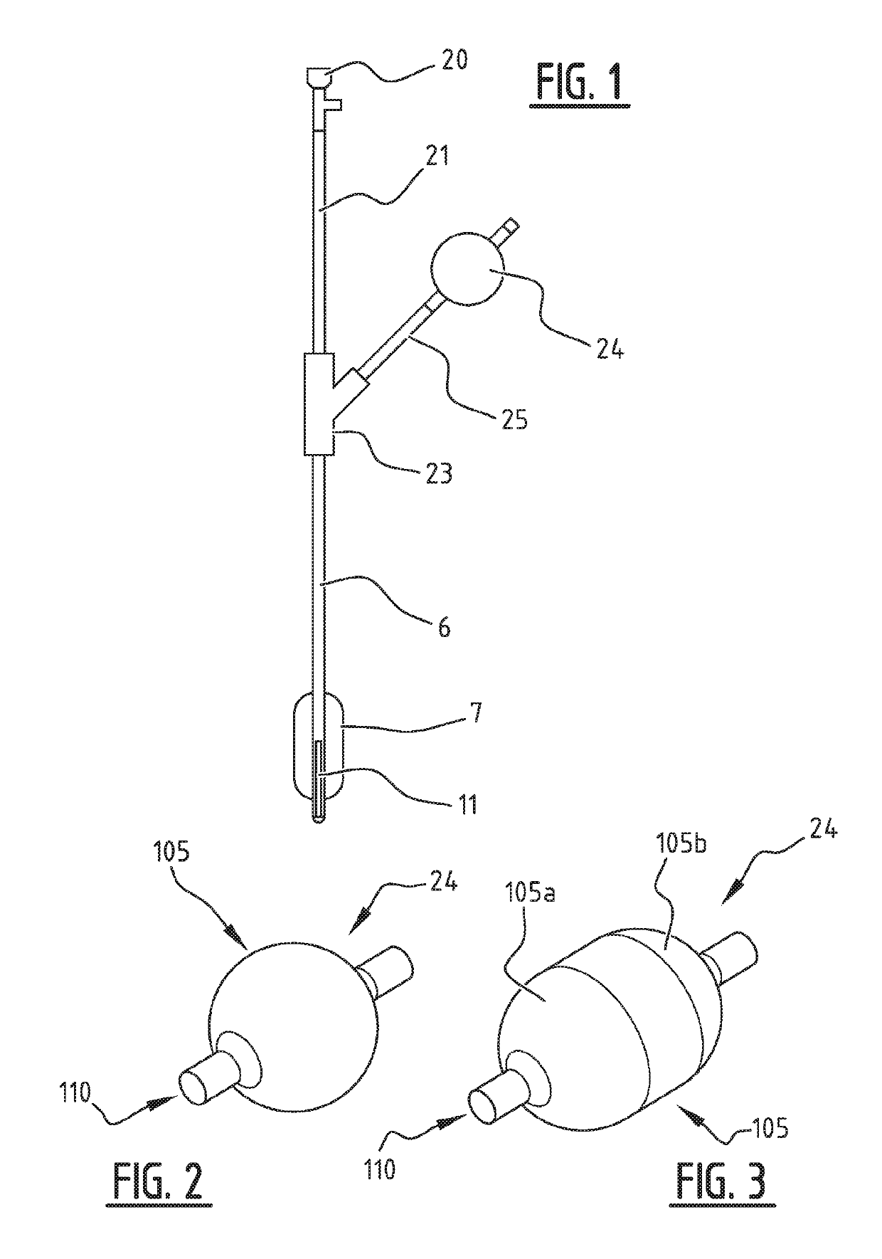
[0006]The object of embodiments of the invention is to provide a system with an inflatable member for positioning in a part of the patient's respiratory tract which allows for an improved pressure control such that damage can be avoided.
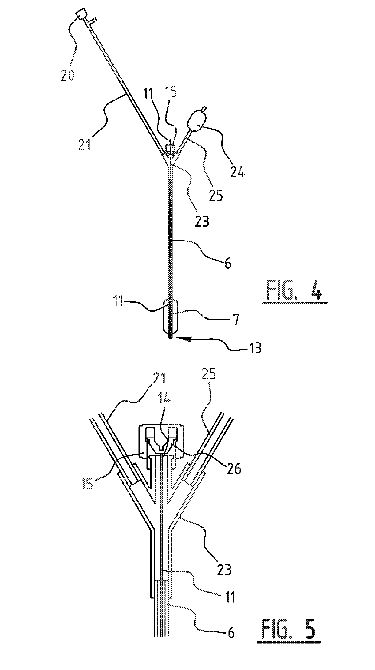
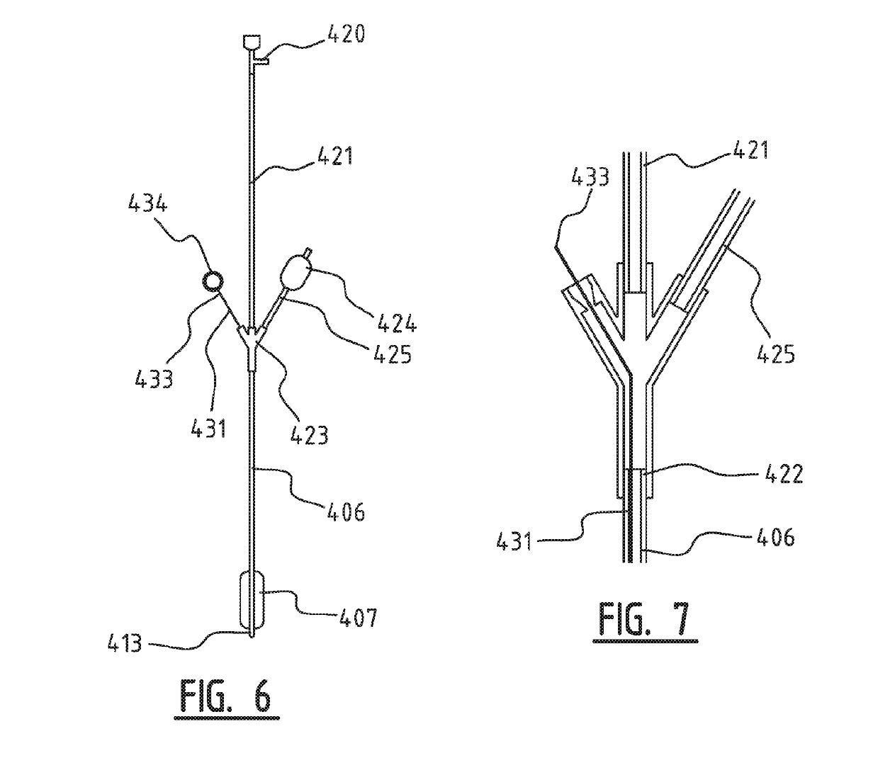
[0008]Embodiments of the invention are based inter alia on the inventive insight that in case of an increase of pressure inside the inflatable member arranged in the respiratory tract, above a predetermined threshold pressure, the elastically expandable balloon will expand rather than the inflatable member. The balloon is located outside the patient, and the increase in volume thereof will limit the pressure increase within the inflatable member, resulting in no or less damage to the trachea wall.
[0010]According to an exemplary embodiment, the system further comprises an imaging device, preferably an ultrasonic imaging device, configured to be arranged in or on the patient's body; wherein said fluid is an imaging liquid. The above system enables the transmission of the ultrasound waves through the imaging liquid in the inflatable member without absorption by the air in the respiratory tract, and enables a safe evaluating of an organ in a patient's body by ultrasound.
[0011]According to another exemplary embodiment, the volume of the elastically expandable balloon, in the non-expanded state, is at least 10 percent of the volume of the inflatable member. In this way the volume of the elastically expandable balloon may be large enough to absorb the influx of excessive fluid coming from the inflatable member in case of increasing pressure within the respiratory tract.
[0020]According to a further developed embodiment, the predetermined threshold pressure of the system lies in a range between 30 and 70 mm Hg. The elastically expandable balloon will expand when the pressure exceeds the predetermined threshold, thereby buffering the pressure increase in the inflatable member within the respiratory tract, so that damage to the trachea wall can be avoided.
[0032]According to yet another exemplary embodiment, the system further comprises a breathing tube having a first end and a second end. The first end of the trachea tube is adapted for connection to a source of respiratory gas, and the second end is adjacent to and surrounded by the inflatable member. In this way during mechanical ventilation of the patient through the breathing tube, the system forms a gas tight seal against the tracheal wall and prevents aspiration of secretion, meanwhile preventing damage to the tracheal wall when the breathing tube is manipulated. Indeed, manipulating the breathing tube may cause a pressure increase in the inflatable member but this pressure increase will cause the elastically expandable balloon located outside the patient's body to expand avoiding that a high pressure is exerted on the wall of the respiratory tract.

Problems solved by technology

A problem which arises when performing the TEE assisted by an inflatable member placed in the respiratory tract, is that the indirect contact between the TEE probe and the inflatable member via the esophagus and trachea walls, especially during the movement of the TEE probe in the esophagus, causes a large increase in pressure within the inflatable member.
If the pressure applied to the trachea wall is too much, it causes potential tissue damage to the trachea.
Also in other applications where a device is manipulated close to an inflatable member placed in the respiratory tract, a pressure increase within the inflatable member may lead to damage of the trachea.

Method used


Image

  • Improved system with an inflatable member for being arranged in the patient's respiratory tract
  • Improved system with an inflatable member for being arranged in the patient's respiratory tract
  • Improved system with an inflatable member for being arranged in the patient's respiratory tract

Examples


Embodiment Construction

[0043]For purposes of the description hereinafter, the terms “upper”, “lower”, “right”, “left”, “vertical”, “horizontal”, “top”, “bottom”, “lateral”, “longitudinal” and derivatives thereof shall relate to the invention as it is oriented in the drawing figures. However, it is to be understood that the invention may assume various alternative variations and step sequences, except where expressly specified to the contrary. It is also to be understood that the specific devices and processes illustrated in the attached drawings, and described in the following specification, are simply exemplary embodiments of the invention. Hence, specific dimensions and other physical characteristics related to the embodiments disclosed herein are not to be considered as limiting.

[0044]It is to be understood that the invention may assume various alternative variations and step sequences, except where expressly specified to the contrary. It is also to be understood that the specific devices and processes...


PUM


Abstract

A system with at least one inflatable member configured for being arranged in a part of the patient's respiratory tract includes a catheter carrying the at least one inflatable member. The catheter includes a fluid line for filling the inflatable member with a fluid; and a pressure monitoring and control member to be arranged outside the patient's body. The pressure monitoring member is in fluid communication with the inflatable member and is configured to receive, during operation, fluid from the inflatable member when the pressure increases above a predetermined threshold pressure and to return the received fluid when the pressure decreases below said predetermined threshold pressure. The pressure monitoring and control member is an elastically expandable balloon made from a material configured to expand elastically when the pressure in the balloon increases above a predetermined threshold pressure and to contract when the pressure decreases below said predetermined threshold pressure.

Description

TECHNICAL FIELD[0001]The present invention relates to a system with an inflatable member configured for being arranged in a part of the patient's respiratory tract.BACKGROUND OF THE INVENTION[0002]Transesophageal echocardiography (TEE) is an ultrasonic imaging method widely used imaging technique for evaluating cardiac structure, function, and valvular anatomy. TEE has also provided a new perspective on the thoracic aorta, and there is growing evidence that the technique contributes valuable and sometimes unique information about aortic structure and pathology.[0003]TEE involves introducing an echo probe into the patient's esophagus and transmitting ultrasound waves across the thorax in the direction of the heart and aorta. However, visualization of the ascending aorta by internal TEE is limited by an air structure, i.e. the trachea and main left and right bronchi. This is due to an important physical limitation of ultrasound: absorption of ultrasound waves. This absorption is depen...

Claims


Application Information

Patent Timeline
Patent Type & Authority Applications(United States)
IPC IPC(8): A61B8/00A61B8/12A61M25/10
CPCA61B8/0883A61M25/0102A61B8/4281A61B8/12A61M25/10187A61M2205/3382A61B8/445
Inventor NIERICH, ARNO
Owner STROKE2PREVENT
Why Eureka
Try Eureka