Field emission device and field emission method

a field emission device and field emission technology, applied in the direction of x-ray tubes, x-ray tube cathode movement, x-ray tube cathode assembly, etc., can solve the problem that the guard electrode etc. cannot properly undergo the regeneration process, and achieve the effect of improving the characteristics of the electric field radiation devi

Active Publication Date: 2019-10-31
MEIDENSHA ELECTRIC MFG CO LTD
View PDF0 Cites 1 Cited by
  • Summary
  • Abstract
  • Description
  • Claims
  • Application Information

AI Technical Summary

Benefits of technology

[0017]According to the present invention described above, it is possible to perform the regeneration process of the guard electrode etc. while suppressing the field em

Problems solved by technology

However, when the voltage of the regeneration process is merely applied across the guard electrode etc., field emission (e.g. field emission before performing th

Method used


Image

  • Field emission device and field emission method
  • Field emission device and field emission method
  • Field emission device and field emission method

Examples


embodiment 1

of Electric Field Radiation Device

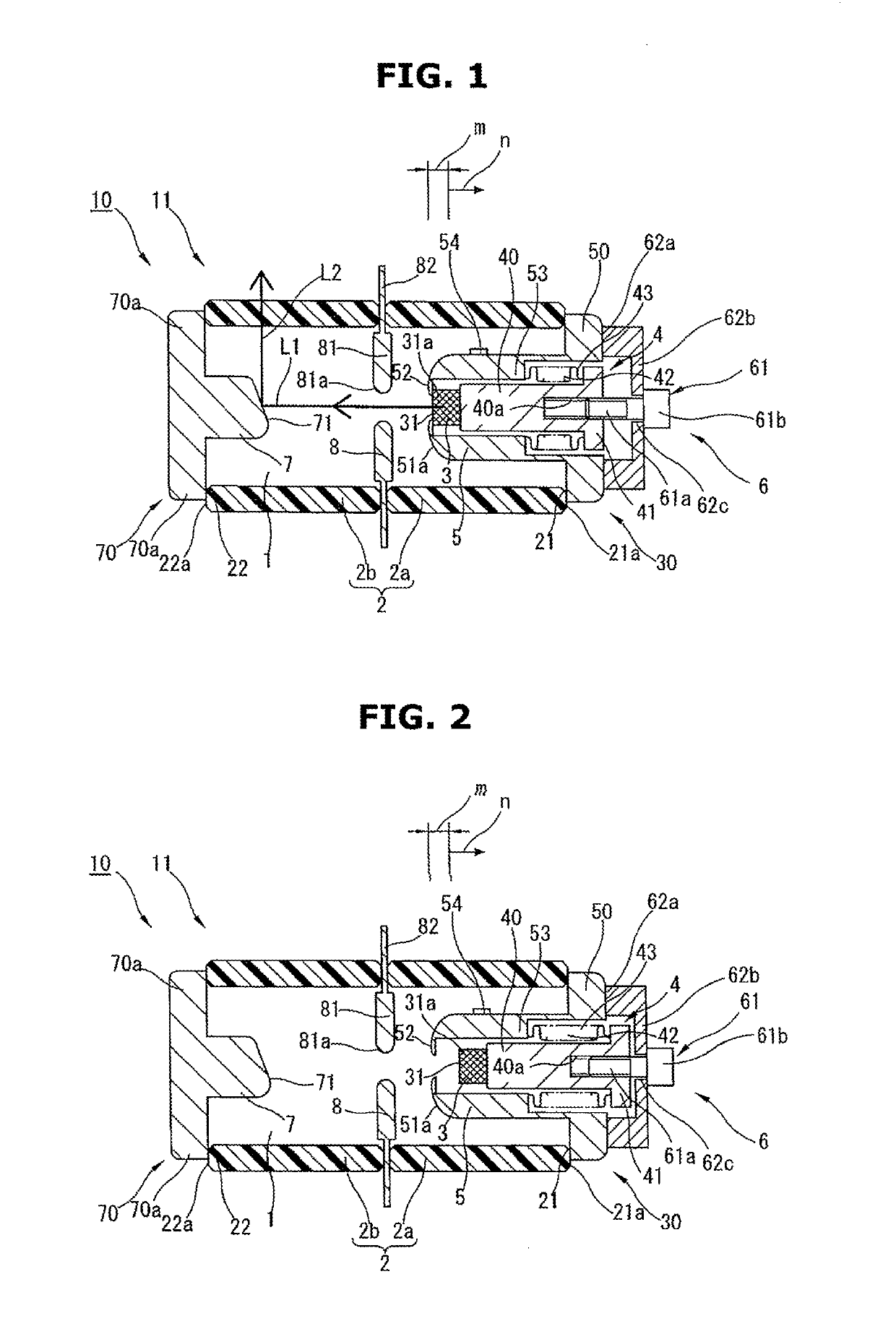
[0037]A reference sign 10 in FIGS. 1 and 2 is an example of an X-ray apparatus to which the electric field radiation device of the present embodiment is applied. In this X-ray apparatus 10, an opening 21 at one end side of a tubular insulator 2 and an opening 22 at the other end side are sealed with an emitter unit 30 and a target unit 70 respectively (e.g. by brazing), and a vacuum enclosure 11 having a vacuum chamber 1 at an inner wall side of the insulator 2 is defined. Between the emitter unit 30 (an after-mentioned emitter 3) and the target unit 70 (an after-mentioned target 7), a grid electrode 8 that extends in a crossing direction of the vacuum chamber 1 (a direction crossing the both end directions, hereinafter, simply called crossing direction) is provided.

[0038]The insulator 2 is formed of insulation material such as ceramic. As the insulator 2, various shapes or forms can be employed as long as they can isolate the emitter unit 30 (the e...

embodiment 2

of Electric Field Radiation Device

[0067]A reference sign 10A in FIG. 5 is another example of an X-ray apparatus to which the electric field radiation device of the present embodiment is applied. Here, in FIG. 5, the same element or component as that of FIGS. 1 to 4A and 4B is denoted by the same reference sign, and its explanation will be omitted below.

[0068]The X-ray apparatus 10A has the same configuration as that of the X-ray apparatus 10, and the operating unit 6 has a motor 63 for turning the adjustment screw portion 61. The motor 63 is fixed to and retained by a circumferential edge side of the bottom 62b of the bearing portion 62 at a predetermined distance away from one end side of the adjustment screw portion 61 by brazing etc. through an insulative tubular column 63b so that a drive shaft 63a is positioned concentrically with a screw shaft of the adjustment screw portion 61. Further, the drive shaft 63a of the motor 63 and the screw head 61b of the adjustment screw portion...

embodiment 3

of Electric Field Radiation Device

[0075]A reference sign 10B in FIG. 6 is other example of an X-ray apparatus to which the electric field radiation device of the present embodiment is applied. Here, in FIG. 6, the same element or component as that of FIGS. 1 to 4A and 4B is denoted by the same reference sign, and its explanation will be omitted below.

[0076]The X-ray apparatus 10B is different from the X-ray apparatuses 10 and 10A to which the operating unit 6 by the screw mechanism is applied. The X-ray apparatus 10B has a configuration employing an operating unit 6B by a reciprocating mechanism, for instance, like an air cylinder 64 shown in FIG. 6.

[0077]This operating unit 6B has the air cylinder 64 that reciprocates the movable body 40 of the emitter supporting unit 4 in the both end directions. The air cylinder 64 is fixed to and retained by the flange portion 50 at a predetermined distance away from the one end side of the movable body 40 (in the drawing, away from a protrusion...


PUM


Abstract

An emitter (3) and a target (7) are arranged so as to face each other in a vacuum chamber (1), and a guard electrode (5) is provided at an outer circumferential side of an electron generating portion (31) of the emitter (3). The emitter (3) is supported movably in both end directions of the vacuum chamber (1) by the emitter supporting unit (4) having a movable body (40). The emitter supporting unit (4) is operated by an operating unit (6) connected to the emitter supporting unit (4). By operating the emitter supporting unit (4) by the operating unit (6), a distance between the electron generating portion (31) of the emitter (3) and the target (7) is changed, and a position of the emitter (3) is fixed at an arbitrary distance, then field emission is performed with the position of the emitter (3) fixed.

Description

TECHNICAL FIELD[0001]The present invention relates to a field emission device (an electric field radiation device) and a field emission method (an electric field radiation method) that are applied to various devices such as an X-ray apparatus, an electron tube and a lighting system.BACKGROUND ART[0002]As an example of the electric field radiation device applied to various devices such as the X-ray apparatus, the electron tube and the lighting system, there has been known a configuration in which voltage is applied between an emitter (an electron source formed of carbon etc.) and a target which are positioned (which are separated at a predetermined distance) while facing to each other in a vacuum chamber of a vacuum enclosure, an electron beam is emitted by field emission (by generation of electrons and emission of the electrons) of the emitter, and by colliding the emitted electron beam with the target, a desired function (for instance, in the case of the X-ray apparatus, a radiosco...

Claims


Application Information

Patent Timeline
IPC IPC(8): H01J35/06H01J35/12H01J1/304H01J3/02H01J7/18
CPCH01J35/12H01J1/3044H01J2201/30453H01J35/065H01J7/18H01J3/021H01J2235/062H01J2235/064H01J35/066H01J35/16H05G1/32
Inventor TAKAHASHI, DAIZOHATANAKA, MICHIHIRO
Owner MEIDENSHA ELECTRIC MFG CO LTD
Why Eureka
Try Eureka