
Ram-jet and turbo-jet detonation engine

a technology of ram-jet and turbo-jet, which is applied in the direction of engine components, mechanical equipment, jet propulsion plants, etc., can solve the problems of inability to reach hypersonic velocities and inability to reach a greater velocity

Inactive Publication Date: 2019-11-07
KOZHEVNIKOV DMITRY DMITRIEVICH
View PDF0 Cites 4 Cited by
  • Summary
  • Abstract
  • Description
  • Claims
  • Application Information

AI Technical Summary

Benefits of technology

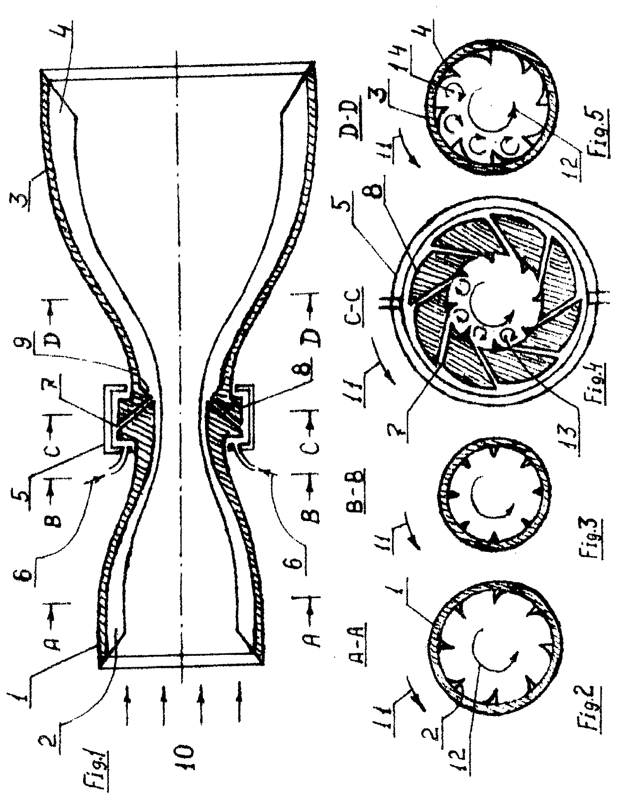
The present invention is a new type of engine for flying apparatus that can produce thrust at zero velocity and run continuously with changes in speed. This engine is called the Ram-jet and turbo-jet detonation engine (RTDE). The invention includes a design that increases the air speed through the engine by adding blades-spirals that accelerate the airflow. This allows for a faster increase in air speed and better performance of the engine.

Problems solved by technology

It's impossible to reach a greater velocity because of the engine and the geometry of airflow redirecting channels, i.e. airflow direction.
The majority of hybrid engines, that are able to run at a velocity ratio from zero up to supersonics has no (or a small) direct straight-flow channel, and airflow deviates from rectilinear motion, which is why it's impossible to reach hypersonic velocities with such engines.

Method used


Image

  • Ram-jet and turbo-jet detonation engine

Examples


Embodiment Construction

.

[0080]The Simplest Embodiment (FIG. 1).

[0081]All the rotating elements during the production are integrated into a single integrated detail, the inner blades of which, having a helix form, are screwed in one direction (clock-wise or counter clock-wise), while changing by its form, height and spacing, extending from the beginning of the inlet cone and to the end of the exhaust section.

[0082]The blades have minimal height in the narrow middle section of the channel (possibly, the height can be zero—the absence of the blades in the portion of the maximum conversion of the channel).

[0083]An inlet cone (fan / compressor) 1 (FIG. 1) with blades-spirals is configured to:

[0084]a) at subsonic velocity of the FA,[0085]provide the rotation of the input (countercurrent) airstream 10 (FIG. 1) in the center of the channel in the direction 12 (FIG. 2) by rotating the cone 1 in the direction 11, wherein the air pressed by the centrifugal force to the inner perimeter of the inlet cone, thus, increasi...


PUM


Abstract

A ram-jet and turbo-jet detonation engine includes an inlet part and a discharge part both shaped as axis-symmetrical round hollow rotating cones interconnected by a narrow middle part, having vanes, mounted on the internal surfaces of the cones, not completely overlapping a central part of a channel, and form spirals, twisted about a common central axis of the channel. The inlet cone with vanes serves as a ventilator / compressor, and the discharge cone with vanes serves as a turbine and discharge nozzle. The middle part and the discharge cone are built as one integral component. A centripetal pump supplies fuel to a mixing section. The engine includes a firing system, generating short high-voltage electrical pulses, providing for burning of combustible mixture in a detonation mode. The invention enables an independent horizontal take-off of flying apparatus and a possibility of varying / alternating the speed within a range from subsonic to hypersonic.

Description

CROSS-REFERENCE TO RELATED APPLICATIONS[0001]This application is a U.S. national stage application of a PCT application PCT / RU2017 / 000892 filed on 4 Dec. 2017, published as WO2018117904, whose disclosure is incorporated herein in its entirety by reference, which PCT application claims priority of a Russian Federation patent application RU2016150493 filed on 21 Dec. 2016.FIELD OF THE INVENTION[0002]This invention belongs to flight-type engines, specifically to supersonic jet engines.BACKGROUND OF THE INVENTION[0003]Turbojet engines (TJE) are used for flying apparatus (FA) velocity range from zero to low supersonic Mach 2-3 velocities. For velocity range from low supersonic to velocity up to 5 Mach, ramjets are used. When Mach number is more than 5, hypersonic ramjets with straight channel and direct-flow combustion chamber are required.[0004]For a long flight in dense layers of atmosphere at low subsonic velocities rocket engines are useless, as they are inefficient (uneconomic).Prio...

Claims


Application Information

Patent Timeline
Patent Type & Authority Applications(United States)
IPC IPC(8): F01D15/10F02K7/02F02K1/78F02K7/16
CPCF02K1/78F02K7/02F02K7/16F01D15/10F05D2220/80F01D5/03F05D2220/10F05D2250/25F05D2220/76F05D2220/768F05D2250/323F05D2250/324F02K3/025
Inventor KOZHEVNIKOV, DMITRY DMITRIEVICH
Owner KOZHEVNIKOV DMITRY DMITRIEVICH
Learn More