Ultrasonic degassing of hydrocarbon production fluid

a hydrocarbon production fluid and ultrasonic technology, applied in liquid degasification, separation processes, chemistry apparatuses and processes, etc., can solve the problems of tens of thousands of dollars of losses per well, indirect financial losses, and production fluid may be rejected, so as to reduce the gas content of production fluid and reduce the vapor pressure of production fluid.

Active Publication Date: 2019-11-14
CONOCOPHILLIPS CO
View PDF2 Cites 6 Cited by
  • Summary
  • Abstract
  • Description
  • Claims
  • Application Information

AI Technical Summary

Benefits of technology

[0005]Applicants have recognized that processing hydrocarbon production fluid (referred to here as “production fluid”) is an important aspect of hydrocarbon production, distribution and refining, especially in view of the importance that production fluid have a suitable composition, such as a minimal amount of water or entrained gases, to meet requirements for production fluid distribution and use. The importance is ever increasing as requirements for production fluid composition are becoming more stringent. Applicants have recognized that lowering the gas content of production fluids can reduce the vapor pressure of the production fluid, and that it can

Problems solved by technology

Unfortunately, if production fluid does not meet requirements, the production fluid may be rejected.
This can result in direct financial losses due to lost sales of the production fluid, and indirect financial losses associated with further processing of the production fluid to meet requirements, or shut-in of the well from which the production fluid was produced.
This can amount to tens-of-thousands of dollars of losses per well, per day.
Applicants have recognized that although some existing production fluid processing techniques are suitable for certain conditions and for certain requirements, existing production fluid processing techniques may not be capable of meeting requirements under certain conditions, especially in the case of heightened requirements.
Although such heating and pressure based techniques can be suitable for certain conditions, they may not be suitable for other conditions.
For example, although these techniques can be suitable for use in warm climates, where the required heating is

Method used


Image

  • Ultrasonic degassing of hydrocarbon production fluid
  • Ultrasonic degassing of hydrocarbon production fluid
  • Ultrasonic degassing of hydrocarbon production fluid

Examples


Embodiment Construction

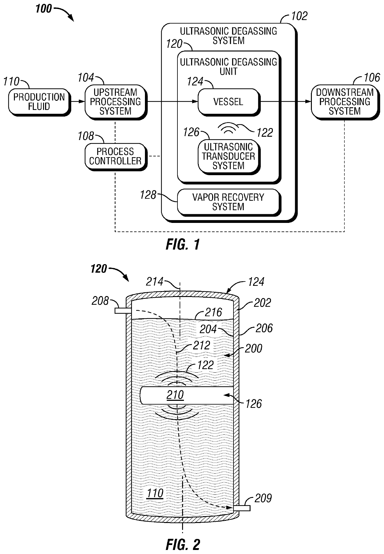
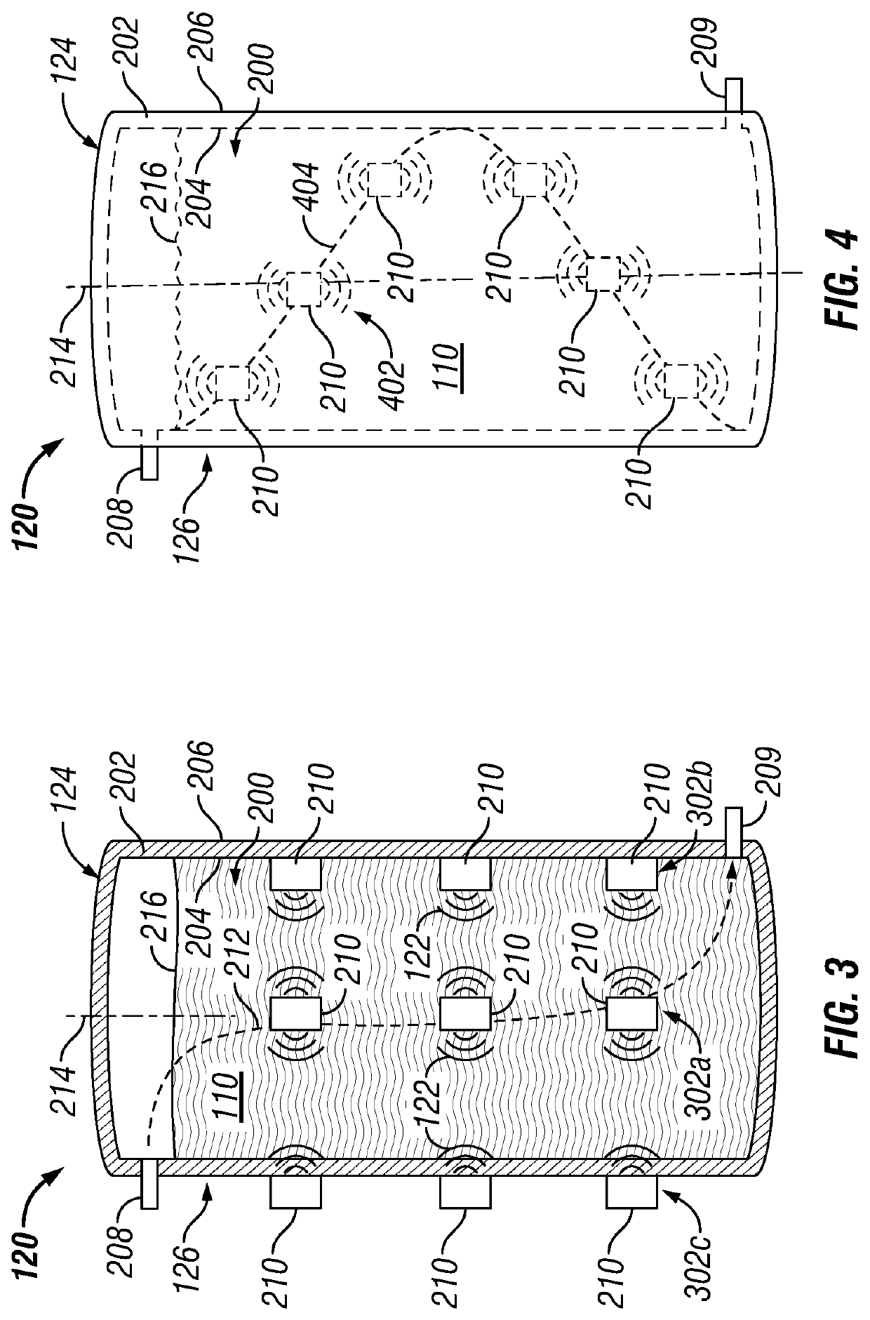
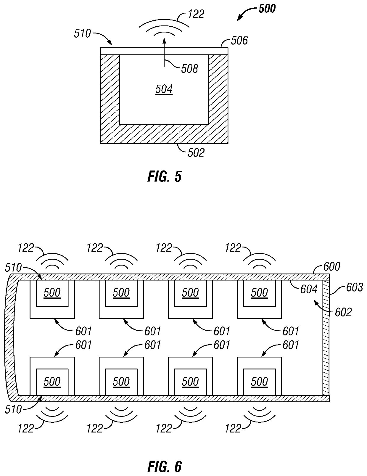
[0031]Described are embodiments of novel systems and methods for degassing hydrocarbon production fluid using ultrasonic signals. In some embodiments, an ultrasonic signal is introduced into production fluid including a hydrocarbon fluid mixture of a hydrocarbon liquid and gas entrained in the hydrocarbon liquid (or “entrained gas”), to facilitate the separation and removal of the entrained gas from the hydrocarbon liquid. In some embodiments, an ultrasonic hydrocarbon production fluid degassing system includes a hydrocarbon degassing unit, including a vessel (e.g., a vapor recovery vessel) that directs production fluid along a flowpath, and an ultrasonic transducer system that transmits ultrasonic signals into the production fluid as it travels along the flowpath. The ultrasonic signals cause the entrained gas to separate from the hydrocarbon liquid, and the gas is removed, for example, by way of a vapor recovery system (VRS).

[0032]In some embodiments, the ultrasonic signals have a...


PUM

PropertyMeasurementUnit
Frequencyaaaaaaaaaa
Frequencyaaaaaaaaaa
Frequencyaaaaaaaaaa

Abstract

Provided are embodiments that include a hydrocarbon fluid processing system including an ultrasonic hydrocarbon degassing unit including a vapor recovery vessel adapted to direct flow of a hydrocarbon fluid mixture along a flowpath extending through an interior of the vapor recovery vessel, and an ultrasonic transducer system disposed inside the vapor recovery vessel and in the flowpath of the hydrocarbon fluid mixture. The hydrocarbon fluid mixture including a hydrocarbon liquid and a gas entrained in the hydrocarbon liquid, the ultrasonic transducer system adapted to transmit ultrasonic signals into the hydrocarbon fluid mixture along the flowpath, and the ultrasonic signals adapted to separate the gas from the hydrocarbon liquid.

Description

FIELD[0001]Embodiments relate generally to processing hydrocarbon production fluid, and more particularly to ultrasonic degassing of hydrocarbon production fluid.BACKGROUND[0002]Production of hydrocarbons, such as oil and natural gas, typically involves extracting the hydrocarbons trapped in a hydrocarbon reservoir of a subsurface formation. During production operations, production fluid containing hydrocarbons is extracted from the reservoir and directed to the surface by way of a well, often referred to as a “hydrocarbon well” or an “oil well”. The production fluid is normally transported to downstream facilities, such as refineries and export terminals, by way of a distribution network of midstream facilities, such as pipelines, tanks and transport vehicles.[0003]In many instances, the production fluid is subjected to various forms of processing to, for example, clean the production fluid of unwanted substances, or otherwise prepare the production fluid for storage, transport and...

Claims


Application Information

Patent Timeline
IPC IPC(8): C10G32/00C10G53/02B01D19/00
CPCC10G32/00B01D19/0078C10G53/02
Inventor PETTY, BRIAN COLT
Owner CONOCOPHILLIPS CO
Why Eureka
Try Eureka