
Radar system and method for receiving and analyzing radar signals

a radar and signal technology, applied in the field of radar system and method for receiving and analyzing radar signals, can solve problems such as harmful artifacts in transmitted signals, and achieve the effects of reducing the quantity of data to be transferred from the receiving element to the controller, reducing the occurrence of artifacts in reconstructed or decoded radar signals, and reducing the amount of data to be transferred

Active Publication Date: 2019-11-21
APTIV TECH LTD
View PDF0 Cites 5 Cited by
  • Summary
  • Abstract
  • Description
  • Claims
  • Application Information

AI Technical Summary

Benefits of technology

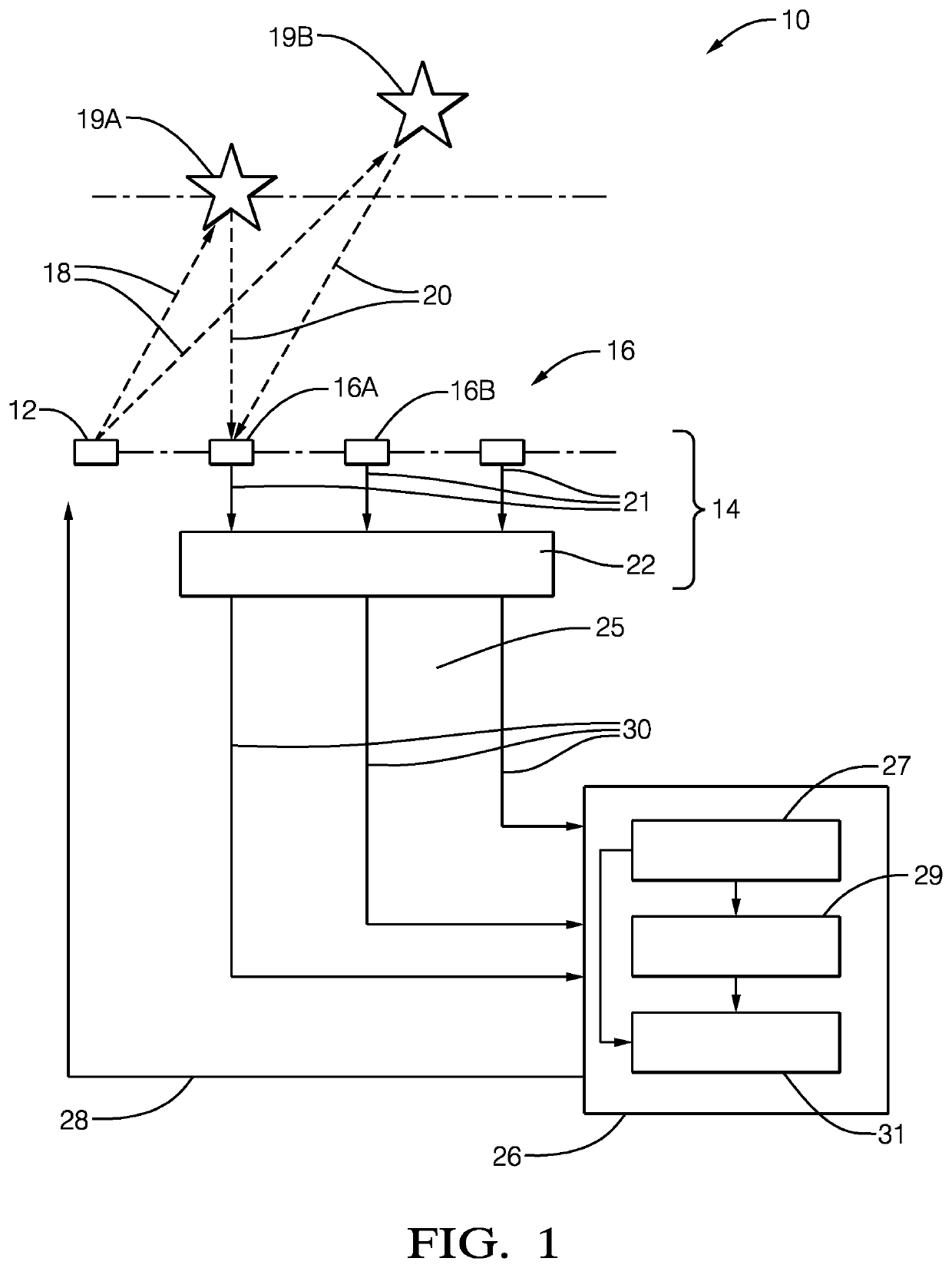
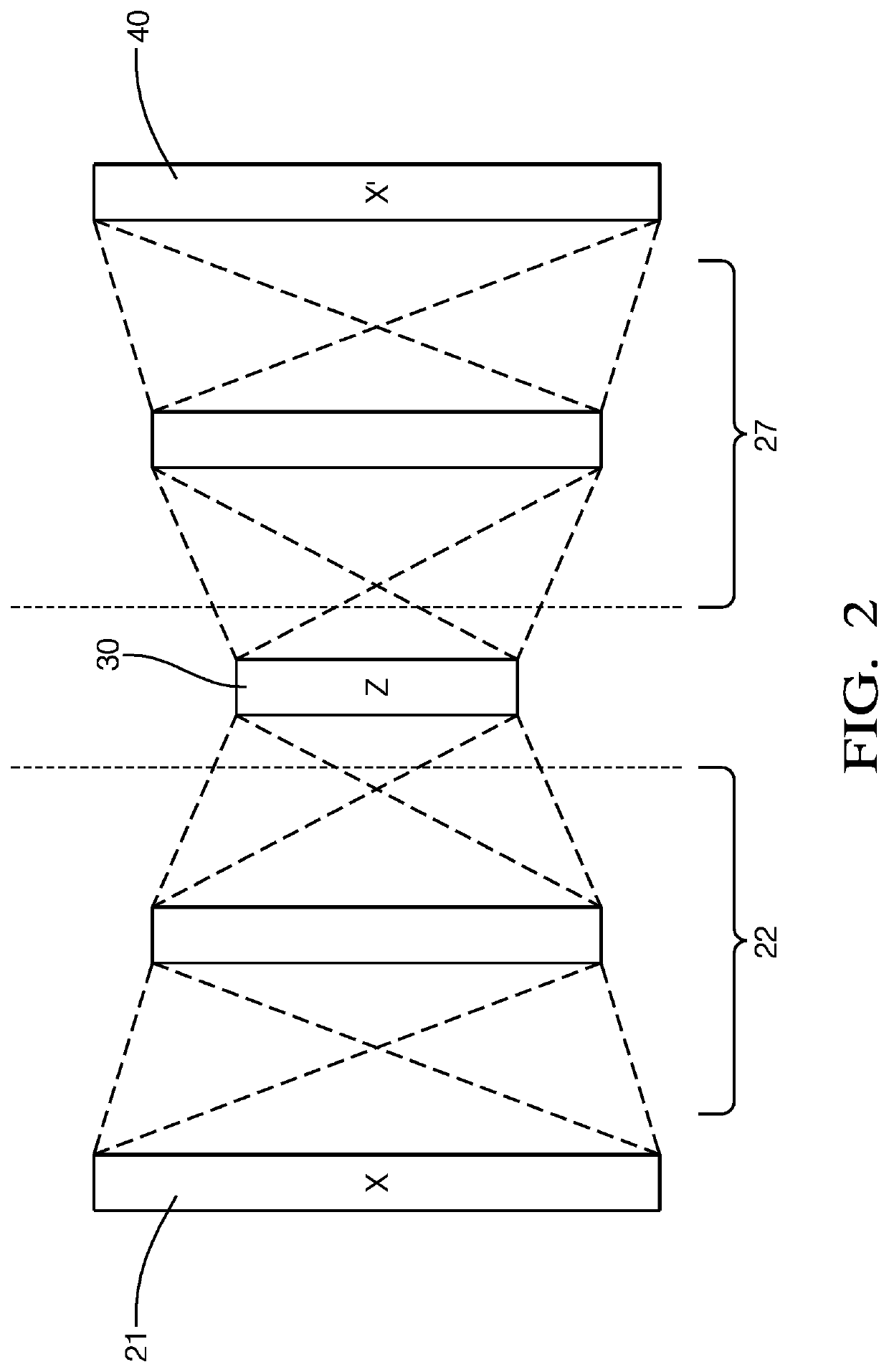
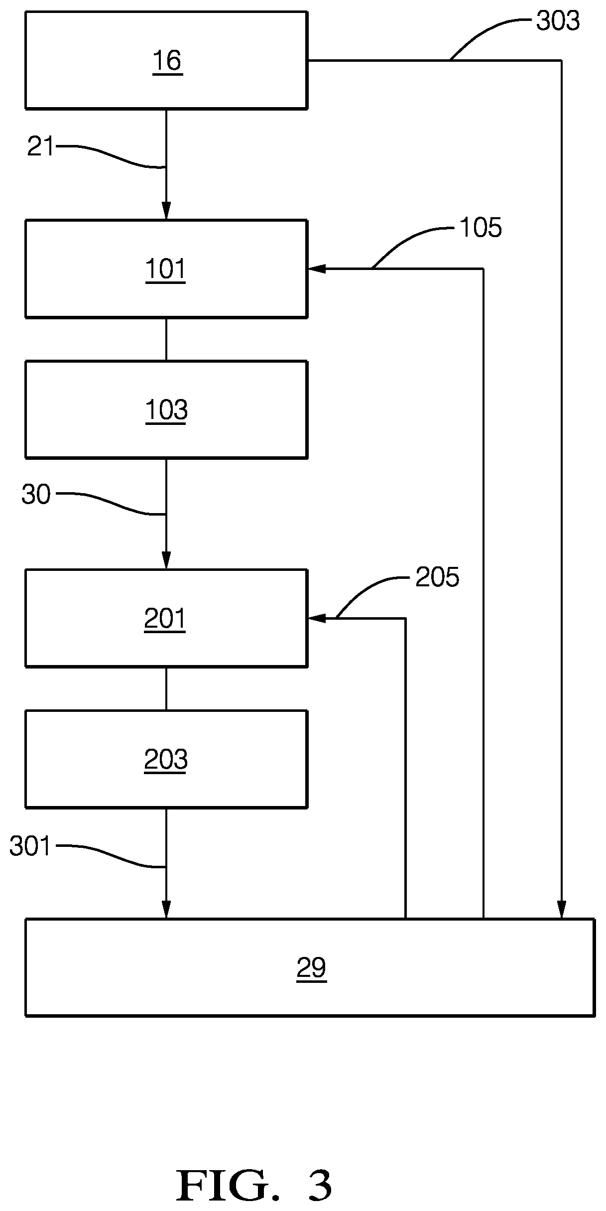
The patent describes an auto-encoding device that can be embedded in a receiving element to provide a compact and easy-to-use solution for receiving and encoding radar signals. This device can be used in automotive applications without the need for an additional encoder. By encoding the original detector signals, the device compresses the data, which reduces the amount of data transfer needed and increases the transfer rate of relevant information. The device can be tailored and optimized for different applications to minimize data loss and reduce unwanted signals. The compression factor is a measure of the ratio of samples of the original detected signals to the number of samples or data sets of the encoded detected signals. The training procedure involves varying parameters of non-linear functions using neural networks until the original and reconstructed signals align with each other. The residual deviation between the original and reconstructed signals can be minimized to optimize the training procedure for different applications. Overall, the device provides a way to efficiently receive, encode, and transfer radar signals with minimal data loss and reduced latency.

Problems solved by technology

Such a compression is necessary since it is not possible to transfer an uncompressed data cube via the data transmission protocols which are currently available in automotive systems.
This assumption is not necessarily true since there are algorithms being able to reduce the effect of noise and to reveal information below noise level.
Furthermore, a compression based on thresholds corresponding to noise levels can introduce harmful artifacts to the transmitted signals.

Method used


Image

  • Radar system and method for receiving and analyzing radar signals
  • Radar system and method for receiving and analyzing radar signals
  • Radar system and method for receiving and analyzing radar signals

Examples


Embodiment Construction

[0031]Reference will now be made in detail to embodiments, examples of which are illustrated in the accompanying drawings. In the following detailed description, numerous specific details are set forth in order to provide a thorough understanding of the various described embodiments. However, it will be apparent to one of ordinary skill in the art that the various described embodiments may be practiced without these specific details. In other instances, well-known methods, procedures, components, circuits, and networks have not been described in detail so as not to unnecessarily obscure aspects of the embodiments.

[0032]‘One or more’ includes a function being performed by one element, a function being performed by more than one element, e.g., in a distributed fashion, several functions being performed by one element, several functions being performed by several elements, or any combination of the above.

[0033]It will also be understood that, although the terms first, second, etc. are,...


PUM


Abstract

A radar system suitable for an automated vehicle comprises at least one receiving element configured to detect reflected radar signals reflected by an object in a field-of-view of the system. The receiving element is further configured to generate detected signals indicative of the reflected radar signals detected by the receiving element. Furthermore, an auto-encoding device performing an auto-encoding operation on the detected signals is embedded in the receiving element such that the receiving element outputs the detected signals in an encoded form.

Description

TECHNICAL FIELD OF INVENTION[0001]This disclosure generally relates to a a radar system suitable for an automated vehicle and to a method for receiving and analyzing radar signals.BACKGROUND OF INVENTION[0002]Radar systems are used for many automotive applications, e.g. for advanced driver assistant systems (ADAS) comprising automatic cruise control (ACC) and / or automatic emergency breaking (AEB). Common radar sensors of such systems, like front facing or side facing radar sensors, provide sensor information in terms of so-called detection lists. These lists comprise properties of physical detections performed on the data signals of the radar sensors. Typically, a detection list comprises the properties of approximately 64 to 128 physical detections. A single detection consists of range, angle, amplitude and velocity information of a target at which a radar signal sent by the radar system is reflected.[0003]Although the detection lists are sufficient for the traditional driver assis...

Claims


Application Information

Patent Timeline
IPC IPC(8): G01S7/41G01S13/931
CPCG01S7/417G01S13/931G01S7/02G01S7/003G01S13/87H03M7/30H03M7/3059G06N3/08G01S2013/9327G06N3/045
Inventor GEBHARDT, PATRIK
Owner APTIV TECH LTD
Learn More