Nozzle and injection device for use in underground coal gasification process and method for operating injection device

a technology of injection device and gasification process, which is applied in the direction of coal gasification, survey, borehole/well accessories, etc., can solve the problems of high back-burn rate, equipment burning, and devices in prior art still having some difficulties in applying high concentration oxidant, so as to improve the safety of the nozzle and ensure the safety of the process, the effect of safe production of stable and high-quality product gas

Active Publication Date: 2019-11-28
ZHONGWEI SHANGHAI ENERGY TECH CO LTD
View PDF0 Cites 4 Cited by
  • Summary
  • Abstract
  • Description
  • Claims
  • Application Information

AI Technical Summary

Benefits of technology

[0029]According to the present invention, the nozzle adopts a structure in which a centre tube is combined with an outer casing, wherein the centre tube is an oxidant pathway, and the annular space between the centre tube and the outer casing is a coolant pathway. The centre tube is connected to the outer casing by a non-sealed spiral connection, and while the non-sealed spiral is used for connection, it also forms a spiral flow pathway for the coolant to pass through, thereby forming a flowing annular cooling jacket on the nozzle, which can effectively cool down the nozzle while the nozzle is in operation, thereby preventing the nozzle from being burnt and having structural deformation in the UCG process, thereby improving the safety of the nozzle.
[0030]Furthermore, according to this invention, the injection equipment is formed by further combining a coiled tubing and a mechanical shearing device behind the nozzle, wherein the coiled tubing, as a conveying device, accurately transports and positions the nozzle, and the mechanical shearing device is able to disconnect the nozzle when necessary to retract the injection device components including the coiled tubing to at least a safe position for subsequent use, and the nozzle is used for injecting reagents such as coolant and oxidant into the underground coal seam. By applying the injection equipment with this configuration, high concentration oxidant can be continuously injected into the underground coal seam, to safely produce stable and high quality of product gas from the underground coal seam.
[0031]In addition, according to this invention, a method of operating the injection device is also provided, wherein the UCG process can be continuously performed using a high concentration oxidant based on the efficient cooling of the nozzle and the safety of the injection equipment used, the retraction cycle and / or retraction distance in the burn-back method of the UCG in the prior art can be further shortened, thereby realizing a substantially continuous UCG process.
[0032]Therefore, the nozzle, the injection equipment and the corresponding injection device operation method of this invention can help to perform the UCG process more safely and efficiently, which brings an advancement to the prior art.

Problems solved by technology

When the oxygen concentration is too high, such as greater than 35 vol %, cooling reagents must be used at the same time to prevent too high temperatures of the combustion zone and excessively high back-burns rates, which is where devices in prior art are still having some difficulties when applying high concentration oxidant.
However, the internal structure of the nozzle (e.g. in the oxidant pathway) is obviously complicated and mostly metal components, so that at a higher oxygen concentration, the metal particles generated by the friction between the metal components may result in particle impingement ignition spontaneous combustion, therefore burning the equipment.
Moreover, when the side hole actuation is controlled by the injection pressure, the pressure fluctuation tends to cause the high-temperature syngas to flow backward into the nozzle and directly make contact with the oxidant, which may cause combustion or explosion inside the nozzle, and resulting in challenges for safe use.
Obviously, such a gasification device also has a relatively complicated structure, and wherein the oxidant delivery pathway is an annular space, which causes the oxidant to be directly exposed to a possible high temperature environment, resulting is challenges for safe use.
CN205243495U discloses a nozzle and a gasification reagent delivery system using the nozzle, wherein the nozzle comprises of a ceramic body and a metal protective sleeve, and the protective sleeve is wrapped around the nozzle body, but wherein the protective sleeve is only used to protect the nozzle and does not have any active cooling mechanisms, and furthermore, there is no reverse flow protection mechanism at all.
Therefore, such nozzles cannot be safely or efficiently used in the UCG for high concentrations of oxidant such as pure oxygen.
This burner considers the cooling mechanism more comprehensively, but the cooling coil wrapped around the outer surface of the component results in high torque and drag forces when the equipment enters and exits the well, and the heat dissipation requirement limits the wall thickness of the cooling coil, so that the cooling coil can be easily damaged in the underground environment.
In addition, there is no reverse flow protection mechanism for the entire burner and conveying system, and resulting in problems for safe use.
Although the patent mentions oxygen-enriched underground coal gasification, the oxygen injection equipment lacks its own cooling mechanism and is not suitable for underground coal gasification with high concentration of oxidant.
However, the casing seal in this patent makes it extremely difficult for the equipment to enter and exit the wellhead and pass through the directional well curvature area, and although the oxidant in this patent can be substantially pure oxygen, the pressure of the water column itself in the water injection pathway makes the controlled retraction process very complex and difficult to implement.

Method used


Image

  • Nozzle and injection device for use in underground coal gasification process and method for operating injection device
  • Nozzle and injection device for use in underground coal gasification process and method for operating injection device

Examples


Embodiment Construction

[0042]This invention will be further described in detail below with reference to the accompanying drawings.

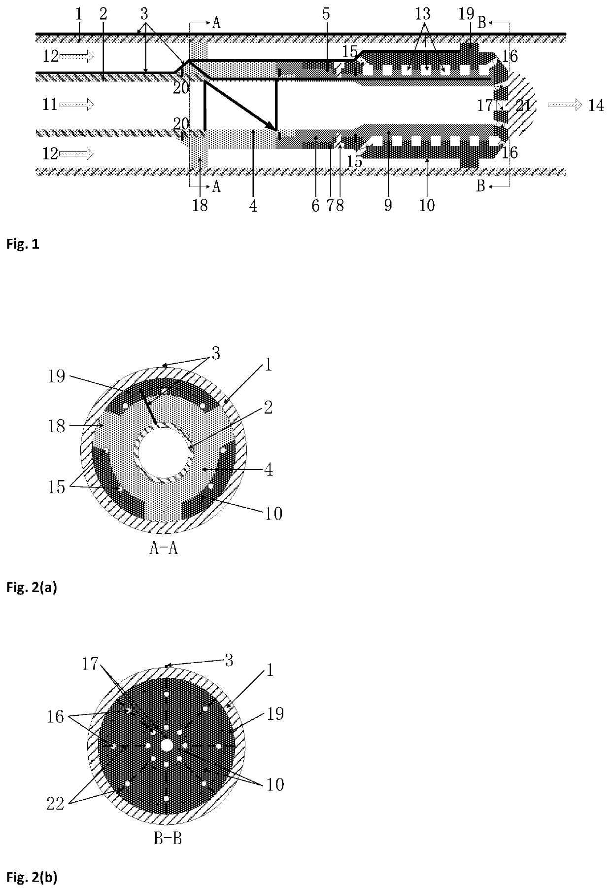
[0043]This invention provides a nozzle for an underground coal gasification (UCG) process, the nozzle comprising a centre tube and an outer casing. The centre tube and the casing extend from the connection end to the injection nozzle end, the two being concentric and are spaced by the annular space in-between them. The outer casing extends from the connection end to form an annular end face and the encapsulating jet end forms an injection nozzle end face, wherein the centre tube and the casing are connected by a non-sealed spiral and thereby forming a spiral flow pathway inside the nozzle annulus, wherein a plurality of coolant inlets and coolant outlets pairs, corresponding to each other and communicating and matching with the spiral flow pathways, are provided on the annular end face of the connection end and the injection nozzle end face, and wherein the injection nozzle end...


PUM


Abstract

An injection device, which comprises a nozzle and which is used for an underground coal gasification process; the nozzle and the injection device are used for continuously injecting a high-concentration oxidant into an underground coal layer during the underground coal gasification process, in which case the high-concentration oxidant may be used safely and steadily to obtain a high-quality and stable product gas, while a retraction cycle and / or a retraction distance of a retraction method in the existing technology may be greatly shortened, thus achieving the continuous and steady operation of the underground coal gasification process. Also disclosed is a method for operating the injection device.

Description

TECHNICAL FIELD[0001]This invention provides a nozzle, an injection device and operating method for the injection device for the underground coal gasification process. In particular, according to this invention, the nozzle and the injection device can be used to continuously inject high concentration of oxidant into an underground coal seam during the underground coal gasification process.BACKGROUND ART[0002]Underground coal gasification (UCG or ISC) is a process by which a coal seam is converted into a product gas, by controlled combustion (incomplete combustion) and gasification reaction of the underground coal seam. The product gas is typically referred to as syngas and can be used in processes such as fuels production, chemical production and power generation. The underground coal gasification process integrates well construction and completion, underground coal mining and coal gasification technology and has the advantages of good safety, low investment, high profit and less po...

Claims


Application Information

Patent Timeline
Patent Type & Authority Applications(United States)
IPC IPC(8): E21B43/295E21B34/06E21B29/00B05B1/00B05B15/14
CPCE21B43/295B05B1/005E21B47/065E21C43/00E21B34/06B05B15/14E21B47/06E21B29/00E21B41/0078E21B47/07E21B43/243E21B10/61
Inventor MIN, ZHENHUAWANG, YUANLIBURGER, CASPER JAN HENDRIK
Owner ZHONGWEI SHANGHAI ENERGY TECH CO LTD
Why Eureka
Try Eureka