Processing Matrix Vector Multiplication

a matrix vector and multiplication technology, applied in the field of processing matrix vector multiplication, can solve the problems of large challenge, similar problems may exist in other hardware systems, and relatively simple problems, so as to reduce the size of the biggest memory block and improve processing speed.

Active Publication Date: 2019-11-28
MYRTLE SOFTWARE LTD
View PDF0 Cites 8 Cited by
  • Summary
  • Abstract
  • Description
  • Claims
  • Application Information

AI Technical Summary

Benefits of technology

[0016]In some embodiments (especially programmable logic circuits), each memory block is part of a different respective memory device. Each element of the vector may be assigned to one or more of the plurality of vector parts, for example based on a structure of the matrix. The step of storing may then be performed in accordance with the assigning. For example, the vector parts may each be stored as a contiguous sequence of elements of the vector (so that one stored vector part may overlap with another stored vector part), stored as (precisely) specified subsets of elements of the vector, stored as a randomly (or pseudo-randomly) selected grouping of elements of the vector or a combination of these options. An alternative approach is for each vector part to comprise a selection of up to one element from each of a plurality of non-overlapping subdivisions of the vector. E

Problems solved by technology

A challenge for implementing matrix vector multiplication evaluation using this technology is to feed a sufficient number of these processors with productive work, in parallel.
Similar problems may exist in other hardware systems.
For dense matrices, this problem is relatively straightforward owing to the regular data access patterns.
The challenge is much greater when multiplying a sparse matrix with a dense vector.
A naïve approach to sparse matrix vector multiplication is to use a dense matrix multiplier as discussed above, but this is highly inefficient.
Such an approach cannot make full use of the arithmetic processors on the board, since only a small proportion of these (given by matrix's density, which may be derived from its sparsity, for example

Method used


Image

  • Processing Matrix Vector Multiplication
  • Processing Matrix Vector Multiplication
  • Processing Matrix Vector Multiplication

Examples


Embodiment Construction

[0027]In a general sense, matrix vector multiplication of the disclosure may consider a matrix of size M×N (that is, M rows and N columns) and a vector of size N (that is, N rows and a single column). The matrix is a sparse matrix including a zero values. Preferably, the density of the sparse matrix is at least 1%. The density of the matrix is no more than or optionally less than 40% (60% sparsity), typically no more than (or less than) 30% (70% sparsity) or 20% (80% sparsity) and more preferably no more than (or less than) 10% (90% sparsity) or 5% (95% sparsity). A density of between 5% and 15% is most preferred, with 6.25% and (less preferably) 12.5% being possible more optimal values.

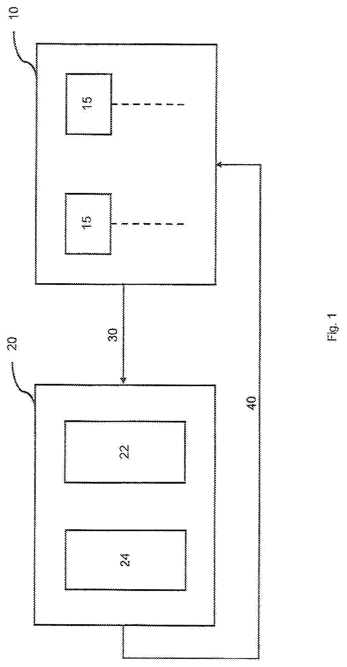
[0028]Referring first to FIG. 1, there is shown a schematic block diagram of a computing system, which can be implemented in accordance with the disclosure. This implementation focuses on an FPGA system, but alternative systems using a similar or equivalent configuration can be considered. The comput...


PUM


Abstract

A size M×N sparse matrix, including zero values, is multiplied with a size N vector, using a processor arrangement. A data storage linked to the processor arrangement stores the matrix in a compressed formal. Zero values are not stored. The data storage stores the vector as vector parts, each of a respective size Ki, 1<Ki<N and i=1 . . . P. A vector part comprises a vector element in common with another vector part. Each vector part is stored in a distinct memory block. Each of a plurality of the non-zero values of a matrix row is associated with a memory block storing an element of the vector having an index corresponding with a respective index of the non-zero value. The processor arrangement multiplies, in parallel, each of the plurality of the non-zero values of the matrix row by the respective vector element having a corresponding index stored in the associated memory block.

Description

CROSS REFERENCE TO RELATED APPLICATION[0001]This U.S. non-provisional patent application claims priority under 35 U.S.C. § 119 to Great Britain Patent Application No. 1808629.8, filed May 25, 2018, with the Intellectual Property Office of the United Kingdom, the content of which is hereby incorporated herein by reference in its entirety.TECHNICAL FIELD OF THE INVENTION[0002]The disclosure concerns multiplication of a matrix of size M×N with a vector of size N, particularly when the matrix is a sparse matrix. A method and / or a computing system for such multiplication operations is provided.BACKGROUND TO THE INVENTION[0003]Multiplication of a matrix by a vector Is a well-established task for computing systems, with applications in a range of scientific and engineering systems, for example computational fluid dynamics, neural networks, robotics and others. Increasingly, specialist computing systems use programmable logic circuits, for example a Field Programmable Gate Array (FPGA), for...

Claims


Application Information

Patent Timeline
IPC IPC(8): G06F17/16G06F3/06G06F16/2455G06F16/901
CPCG06F17/16G06F16/24558G06F16/9024G06F3/0604G06F3/064G06F3/0659G06F3/0673
Inventor PAGE, DAVIDBAAIJ, CHRISTIAANSHIPTON, JONATHANBALDWIN, PETERHAZEL, GRAHAMFOWLER, JONATHAN
Owner MYRTLE SOFTWARE LTD
Why Eureka
Try Eureka