
Implementing ir reflective mask to minimize cte mismatch between laminate and pth copper

a technology of pth copper and reflective mask, applied in the field of data processing, can solve the problems of fatigue failure mode, large strain in the embedded copper structure, thermal fatigue of pth barrels, etc., and achieve the effect of increasing pth reliability

Active Publication Date: 2019-11-28
IBM CORP
View PDF0 Cites 0 Cited by
  • Summary
  • Abstract
  • Description
  • Claims
  • Application Information

AI Technical Summary

Benefits of technology

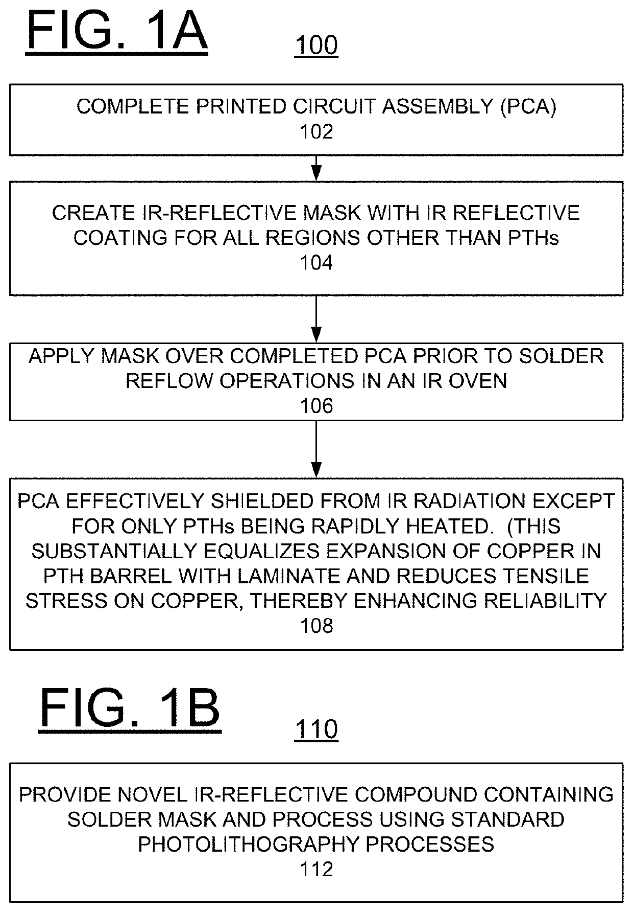
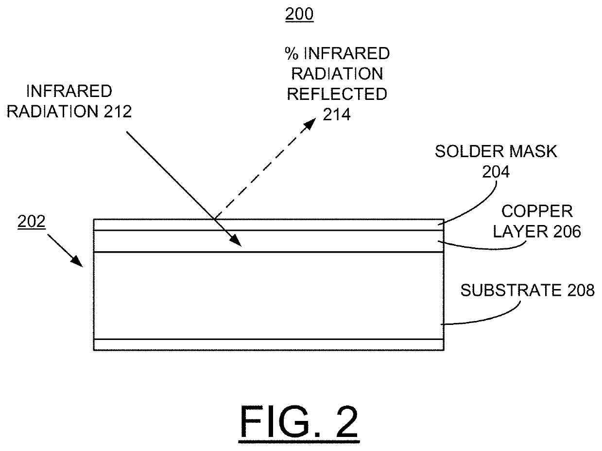
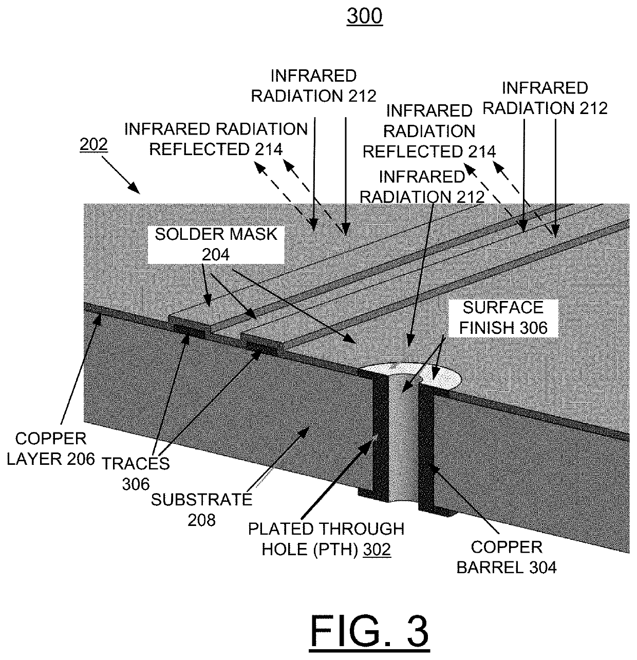
The present invention provides a method and structure for manufacturing a printed circuit board (PCB) with an infrared (IR) reflective mask to minimize a coefficient of thermal expansion (CTE) mismatch between the PCB laminate and plated through hole (PTH) copper. The IR reflective mask reduces the rate of heating of the PCB laminate while allowing the PTH copper to expand without experiencing significant tensile strain, thus increasing the reliability of the PCB. The IR reflective mask is placed over the completed PCB assembly prior to solder reflow operations, resulting in a more uniform expansion of the copper in the PTH barrel and reduced tensile stress on the copper. Additionally, the IR reflective mask helps to shield the PTH from excess IR radiation, further improving the reliability of the PCB.

Problems solved by technology

Thermal fatigue of PTH barrels is a significant issue in electronics reliability.
The difference in coefficients of thermal expansion between the metal plating of the through hole and the laminate, typically a fiberglass / epoxy resin composite, causes a large enough strain in the embedded copper structures to induce a fatigue failure mode during thermal cycling or solder reflow operations.
This difference in CTE drives stress into the plated copper and can result in barrel cracks.

Method used


Image

  • Implementing ir reflective mask to minimize cte mismatch between laminate and pth copper
  • Implementing ir reflective mask to minimize cte mismatch between laminate and pth copper
  • Implementing ir reflective mask to minimize cte mismatch between laminate and pth copper

Examples


example fabrication

[0030 of the IR mask 406 is provided at: (http: / / www.cnf.cornell.edu / cnf_process_mask_equipment.html), by Cornell Nanoscale Science and Technology Facility, as follows:

[0031]Optical lithography requires the fabrication of a mask. Generally, photomasks consist of a piece of glass of some type, coated with a film in which the pattern is formed. A layer of sputtered Cr about 100 nm thick coats the glass plate. Resist is then spun on the plate, and the exposure is made. After development, the Cr is removed from the unprotected areas with an acid etch, and an image of the pattern is left in the Cr. The exposure can be made with either an optical or an electron beam lithography tool. Once the pattern is formed, a second, IR reflective coating is applied to those regions of the glass master that do not define the PTHs. Various IR reflective coatings can be used, such as found at: (https: / / www.pcimag.com / articles / 83468-introduction-to-ir-reflective-pigments).

[0032]For example, as described ...


PUM

PropertyMeasurementUnit
temperaturesaaaaaaaaaa
solar reflectanceaaaaaaaaaa
thickaaaaaaaaaa

Abstract

A method and structure are provided for implementing manufacture of a printed circuit board (PCB) with one of an infrared (IR) reflective mask or a novel solder mask to minimize coefficient of thermal expansion (CTE) mismatch between PCB laminate and plated through hole (PTH) copper. At least one of an IR-reflective mask and a solder mask composition for use in IR reflow processes is created such that radiant heat is reflected away from the major portion of the PCB yet permitted to impinge upon the PTHs. The copper within the PTH expands due to radiant heating while the bulk laminate expansion is significantly reduced due to the reflected IR radiation. Consequently, the CTE mismatch is minimized and tensile strain of the copper in the PTH is reduced, providing enhanced reliability.

Description

FIELD OF THE INVENTION[0001]The present invention relates generally to the data processing field, and more particularly, relates to a method and structure for implementing manufacture of a printed circuit board (PCB) with infrared (IR) reflective mask to minimize coefficient of thermal expansion (CTE) mismatch between PCB laminate and plated through hole (PTH) copper.DESCRIPTION OF THE RELATED ART[0002]Thermal fatigue of PTH barrels is a significant issue in electronics reliability. The difference in coefficients of thermal expansion between the metal plating of the through hole and the laminate, typically a fiberglass / epoxy resin composite, causes a large enough strain in the embedded copper structures to induce a fatigue failure mode during thermal cycling or solder reflow operations.[0003]Recent modelling work has shown that at temperatures approaching 300° C. (lead-free solder reflow temperature=265° C.), the copper in the PTH will expand approximately 0.5% whereas the resin in ...

Claims


Application Information

Patent Timeline
Patent Type & Authority Applications(United States)
IPC IPC(8): H05K3/34G02B5/08B23K1/005
CPCB23K1/0016B23K1/0053G02B5/08H05K3/3494
Inventor O'CONNELL, KEVINPLUCINSKI, MARKTOFIL, TIMOTHYKUCZYNSKI, JOSEPH
Owner IBM CORP
Learn More