Integration of Thermochemical Heat Storage System with Waste heat Recovery Systems

a heat storage system and thermochemical technology, applied in indirect heat exchangers, lighting and heating apparatus, heating types, etc., can solve the problems of limiting the operation capabilities of those systems, no efficient and cost-effective heat preservation means, and limited practicability of waste heat from refrigeration systems

Inactive Publication Date: 2019-12-19
HE JUNYI DEREK +1
View PDF0 Cites 11 Cited by
  • Summary
  • Abstract
  • Description
  • Claims
  • Application Information

AI Technical Summary

Benefits of technology

[0005]It is a principal objective of the present invention to provide a method and a systems for de-coupling the operations of waste heat recovery and the waste heat utilization system which can be applied to the currently existing and widely used conventional refrigeration systems or air conditioning systems in order to make the implementation of waste heat recovery techniques more viable for the applications in residential houses, commercial establishments and industrial processes.
[0006]Another objective of the present invention is to provide a method and a system that the recovery waste heat can be accumulated and stored efficiently with minimum heat loss or even without energy loss.
[0010]The TCS system disclosed in the present invention is based on the salt hydrate technology, the system uses the reaction energy created when salts are hydrated or dehydrated (endothermic / exothermic chemical reaction). It works by storing heat in a vessel containing suitable wet salt. Heat (recovered from refrigeration or air conditioning system) is converted and stored in form of chemical energy by evaporating the water in an endothermic reaction. When water is added again, heat is released in an exothermic reaction. The TCS is a compact way to store heat for a longer time without typical heat losses. This makes it an appropriate solution to overcome the mismatch between seasonal heat supply and demand in temperate climate zones.

Problems solved by technology

However, the waste heat recovery techniques investigated so far are economically feasible for implementation only in industrial refrigeration systems having a large capacity compressor through which large volumes of refrigerant gas are circulated to a condenser, and practical uses of waste heat from refrigeration systems are typically limited to space heating and water heating used for associated industrial processes due to low quality, low temperature of the recovered waste heat.
It has been noted that all these techniques have a common feature that they have to be operated simultaneously in a real time on-line process, meaning that the waste heat recovered has to be consumed simultaneously or immediately after being recovered or consumed in the associated ongoing processes since no efficient and cost-effective heat preserve means are available and implemented.
The mismatching between the available heat supply and demand will limit the operation capabilities of those systems.
That is one of the key factors limiting the implementation of those techniques for waste heat recovery from refrigeration and air conditioning systems.
Another limiting factor is the system capacity requirements since only in industrial refrigeration systems or air conditioning systems having a large compressor capacity, sufficient amount of waste heat can be recovered for practical applications so to make those waste heat recovery techniques viable for practical implementation.

Method used


Image

  • Integration of Thermochemical Heat Storage System with Waste heat Recovery Systems
  • Integration of Thermochemical Heat Storage System with Waste heat Recovery Systems
  • Integration of Thermochemical Heat Storage System with Waste heat Recovery Systems

Examples


Embodiment Construction

[0015]In the description which follows, like parts are marked throughout the drawing with the same reference numerals respectively.

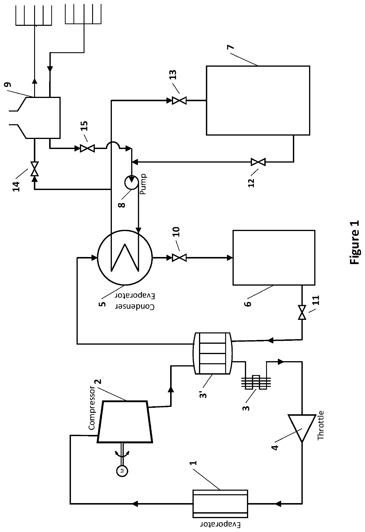
[0016]Referring now to FIG. 1 of the drawing, the waste heat recovery system of the present invention includes an integration of four subsystems: a conventional air conditioning or refrigeration system, a waste heat transfer system, a thermochemical storage system and a waste heat utilization system.

[0017]The conventional air conditioning or refrigeration system consists of an evaporator 1, a compressor 2, a condenser 3, and a throttle 4, they are suitably sized and interconnected to provide air conditioning for a residential house or refrigeration for a commercial establishment such as a show case in a supermarket or refrigeration for an industrial process such as food processing. Air to be conditioned is brought into heat exchanger relation with the evaporator 1 by means of suitable circulation equipment (not shown) into the area being conditioned. An ...


PUM


Abstract

A waste heat recovery for use with refrigeration means and space heating / water heating to meet various seasonal demands on refrigeration and heating energy is disclosed. The system is intended for use with refrigeration means of the conventional type including a compressor and a condenser through which a compressible refrigerant is circulated. The system integrates a refrigeration system and a heating utilization system through a thermochemical system functioning as a heat transfer system and thermochemical energy storage system. Wherein the heat transfer system is used for absorbing the waste heat normally dissipated in the condenser and for discharging the recovered thermal energy to a heat utilization system for space heating and / or water heating, the thermochemical energy storage system is used for converting the waste heat collected into chemical energy for seasonal storage. The waste heat recovery system is designed with a feature that operations of the refrigeration system and the heat utilization system are de-coupled so that the refrigeration system and the heat utilization system can be operated independently at different times on demand. This feature makes implementation of the waste heat recovery system viable for more residential houses, commercial establishments, and industrial processes applications.

Description

FIELD OF THE INVENTION[0001]The present invention relates generally to waste heat recovery system from air conditioning / refrigeration system, in particular relates to such system which recovers the heat wasted during operations of an air conditioning or a refrigeration system, stores the recovered heat in form of chemical energy and releases the stored energy for purpose of water heating and / or space heating as being demand for up to months, event in different seasons.DESCRIPTION OF THE PRIOR ART[0002]The waste heat recovery from refrigeration systems or air conditioning systems has been studied for many years. However, the waste heat recovery techniques investigated so far are economically feasible for implementation only in industrial refrigeration systems having a large capacity compressor through which large volumes of refrigerant gas are circulated to a condenser, and practical uses of waste heat from refrigeration systems are typically limited to space heating and water heatin...

Claims


Application Information

Patent Timeline
Patent Type & Authority Applications(United States)
IPC IPC(8): F28D20/00F28D21/00
CPCF28D2020/0078F28D20/003F28D21/0001F28D2021/0068F24D11/0235F24D2200/31F25B2400/24F28D21/0012F28D2021/0035Y02B10/70Y02B30/12Y02B30/52Y02B30/56Y02E60/14
Inventor HE, JUNYI DEREKHE, CHANGHUA
Owner HE JUNYI DEREK
Why Eureka
Try Eureka