Detector for an optical detection of at least one object

a technology of optical detection and detector, applied in the direction of instruments, sustainable manufacturing/processing, radio-controlled devices, etc., can solve the problems of inefficient use of transversal optical sensors, severe limitation of their applicability range, and upconversion materials, etc., to achieve sufficient signal-to-noise ratio, simple and cost-effective setup, and high intensity

Inactive Publication Date: 2019-12-19
TRINAMIX GMBH
View PDF0 Cites 6 Cited by
  • Summary
  • Abstract
  • Description
  • Claims
  • Application Information

AI Technical Summary

Benefits of technology

[0131]The at least one optional illumination source generally may emit light in at least one of: the ultraviolet spectral range, preferably of 100 nm to 380 nm; the visible spectral range of 380 nm to 760 nm; the infrared spectral range of 760 nm to 1000 μm. Herein, it is particularly preferred when the illumination source may exhibit a spectral range being related to the spectral sensitivities of the transversal optical sensors, in particular, to ensure that the transversal optical sensor illuminated by the respective illumination source may provide a sensor signal with a high intensity, thus, enabling a high-resolution evaluation with a sufficient signal-to-noise-ratio...

Problems solved by technology

Based on intransparent optical properties of the silicon material as employed in this kind of PSD, transversal optical sensors which utilize position-sensitive silicon diodes are, however, intransparent optical sensors, an observation that may be capable of severely limiting their range of applicability.
However, known transversal optical sensors that employ these kinds of materials can, in general, only be used for the optical detection of wavelengths below 1000 nm.
Due to their inefficiency for wavelengths above 1000 nm an upconversion material is usually req...

Method used


Image

  • Detector for an optical detection of at least one object
  • Detector for an optical detection of at least one object
  • Detector for an optical detection of at least one object

Examples


Embodiment Construction

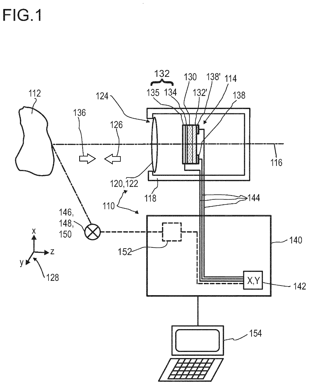
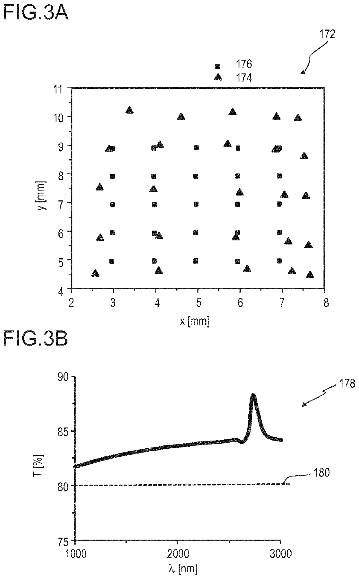
[0285]FIG. 1 illustrates, in a highly schematic fashion, an exemplary embodiment of an optical detector 110 according to the present invention, for determining a lateral position of at least one object 112. The optical detector 110 may preferably be adapted to be used as a detector for a partition of the visible spectral range of 380 nm to 760 nm and / or the infrared spectral range of above 760 nm to 1000 μm, particularly for wavelengths in a spectral range of 380 nm to 15 μm, preferably of 380 nm to 3 μm, specifically of 1 μm to 3 μm. As shown below in FIG. 3B in more detail, the graphene layer 134 may, particularly preferred, exhibit a transmission of at least 80% over a wavelength range of 1 μm to 3 μm. However, other embodiments may also be feasible.

[0286]The optical detector 110 comprises at least one transversal optical sensor 114, which, in this particular embodiment, may be arranged along an optical axis 116 of the detector 110. Specifically, the optical axis 116 may be an ax...


PUM


Abstract

Disclosed herein is a detector including (i) a transversal optical sensor adapted to determine a transversal position of a light beam traveling from the object to the detector, wherein the transversal optical sensor has a photosensitive layer embedded between at least two conductive layers such that at least one of the conductive layers contains an at least partially transparent graphene layer on an at least partially transparent substrate, and wherein the transversal optical sensor generates a transversal sensor signal indicative of the transversal position of the light beam in the photosensitive layer, and (ii) an evaluation device designed to generate at least one item of information on a transversal position of the object by evaluating the at least one transversal sensor signal.

Description

FIELD OF THE INVENTION[0001]The invention relates to a detector for an optical detection of at least one object, in particular, for determining a position of at least one object, specifically a lateral position of the at least one object. Furthermore, the invention relates to a human-machine interface, an entertainment device, a tracking system, a scanning system, and a camera. Further, the invention relates to a method for optical detection of at least one object and to various uses of the detector. Such devices, methods and uses can be employed for example in various areas of daily life, gaming, traffic technology, mapping of spaces, production technology, security technology, medical technology or in the sciences. However, further applications are possible.Prior Art[0002]A large number of optical sensors and photosensitive devices are known from the prior art. While photosensitive devices are generally used to convert electromagnetic radiation, for example, ultra-violet, visible ...

Claims


Application Information

Patent Timeline
IPC IPC(8): H01L27/30G01S17/46H01L31/0224H01L51/44H01L27/146
CPCH01L27/307H01L31/022466G01S7/4816H01L51/442H01L27/14601G01S17/46H01L27/14609Y02E10/549Y02P70/50H10K39/30H10K39/32H10K30/82
Inventor VALOUCH, SEBASTIANHERMES, WILFRIEDBRUDER, INGMARSEND, ROBERTLUNGENSCHMIED, CHRISTOPH
Owner TRINAMIX GMBH
Why Eureka
Try Eureka