Motor drive device

Active Publication Date: 2020-01-09
HITACHI ASTEMO LTD +2
View PDF0 Cites 4 Cited by
  • Summary
  • Abstract
  • Description
  • Claims
  • Application Information

AI Technical Summary

Benefits of technology

[0021]Another aspect of the present invention is that the trailing arm may further include a motor bracket which extends downward from the vehicle body-side attachment portion and to which the motor is attached.
[0022]According to the present invention, the motor can be attached to the trailing arm as a sprung mass with a simple structure.
[0023]Another aspect of the present invention is that the motor drive device may further include a gear transmission mechanism that transmits power of the motor to the wheel. The gear transmission mechanism has a gearbox arrangement attached to the trailing arm as a rigid body. The gearbox arrangement includes a first gearbox and a second gearbox arranged separately from each other, the first gearbox housing a first gear unit disposed about a rotating shaft of the motor, the second gearbox spaced apart from the first gearbox and housing a second gear unit disposed about a rotating shaft of the wheel.
[0024]As the gearbox arrangement o

Problems solved by technology

This motor drive device requires that a relatively large final reduction gear having a differential drive mechanism built-in be mounted on the vehicle body, and thus br

Method used


Image

  • Motor drive device
  • Motor drive device
  • Motor drive device

Examples


first embodiment

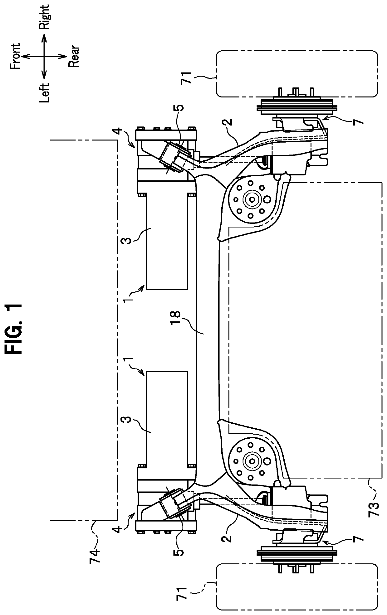
[0065]Referring to FIG. 1, a motor drive device 1 of the present embodiment has trailing arms 2, motors 3 supported by the trailing arms 2 and configured to drive rear wheels 71, gear transmission mechanisms 4 that transmit power of the motors 3 to the rear wheels 71. Hereinafter, a description will be given of the motor drive device 1 that drives the rear wheel 71 on the vehicle left side. The structure of the motor drive device 1 that drives the rear wheel 71 on the vehicle right side is the same except that the layout of the devices are left-right symmetric to each other.

Trailing Arm 2

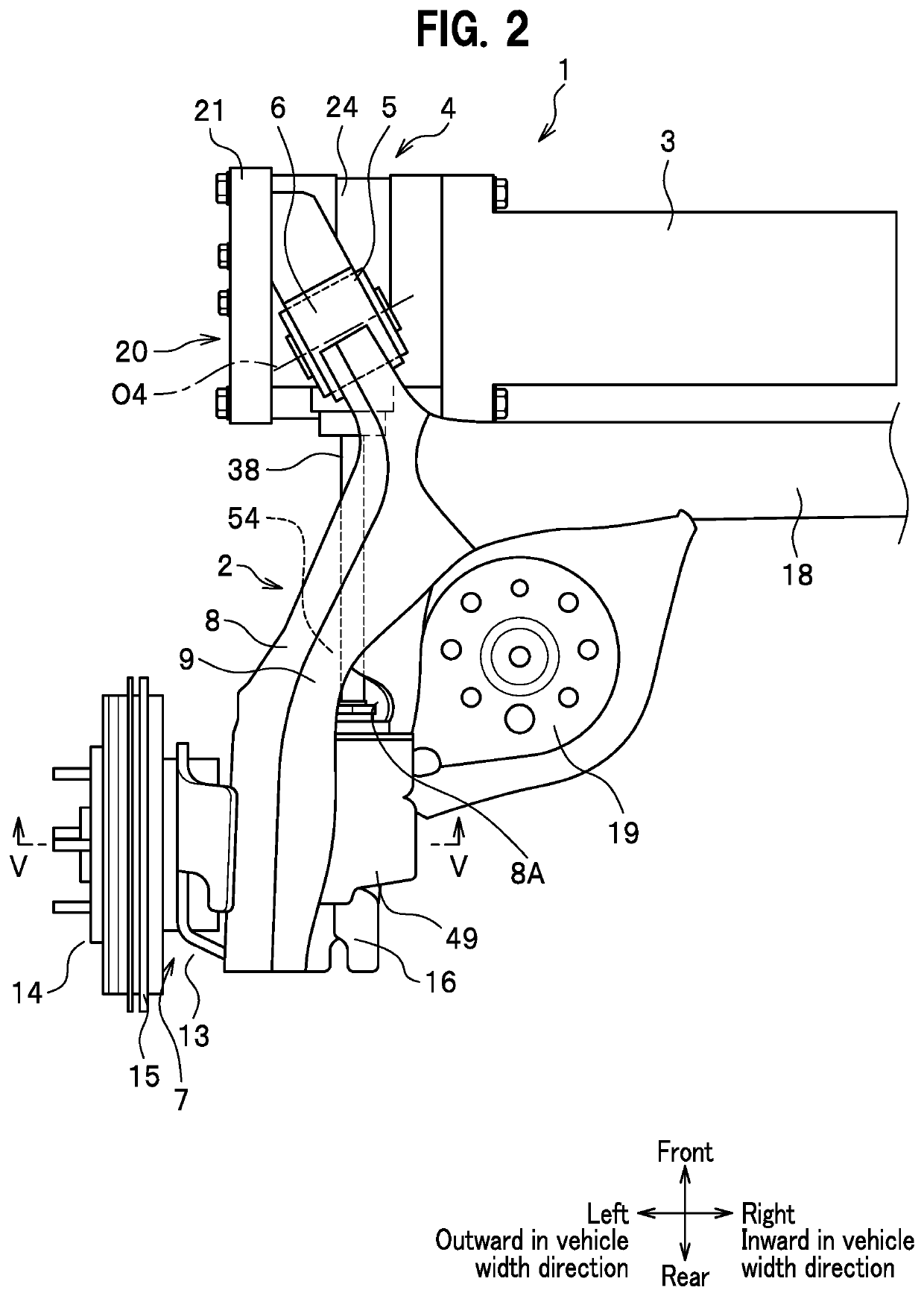
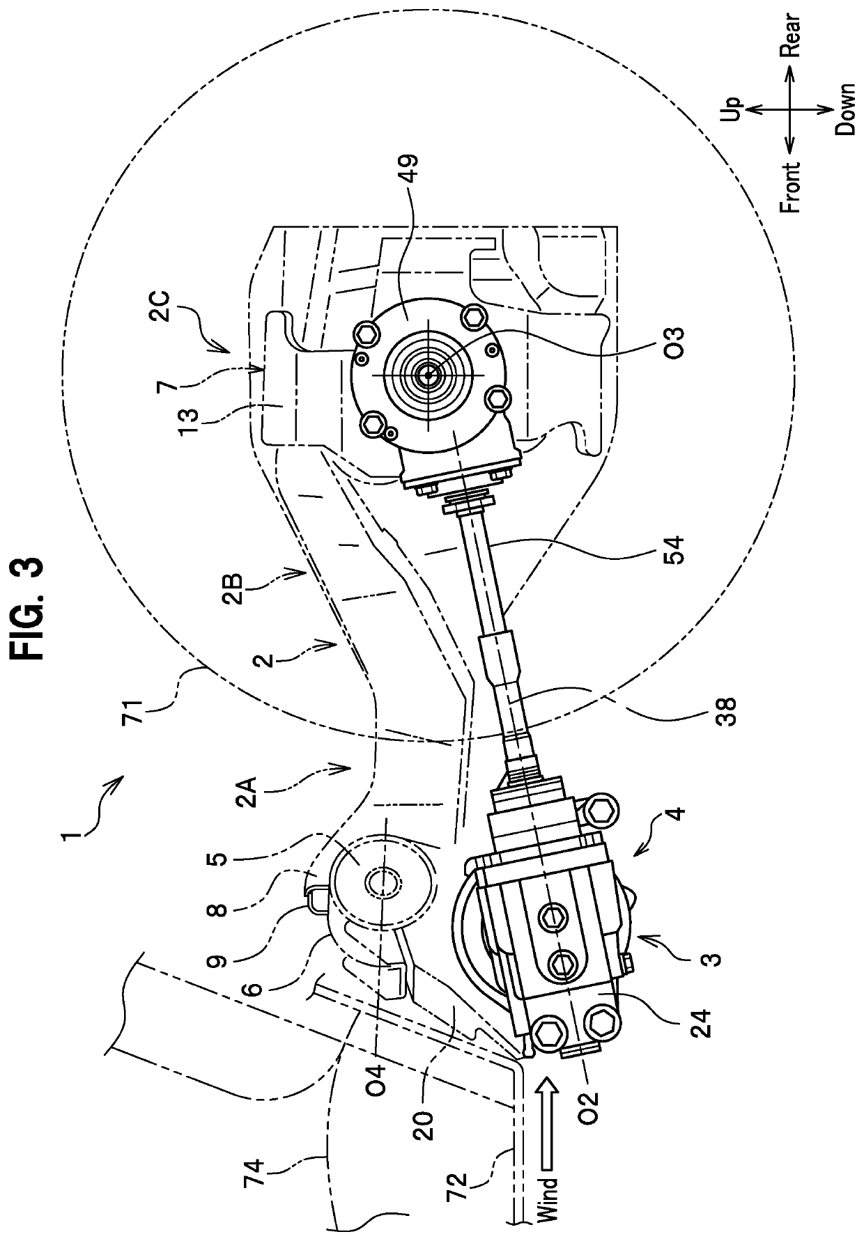
[0066]Referring to FIGS. 2 to 4B, the trailing arm 2 is disposed to extend substantially in the vehicle front-rear direction. The trailing arm 2 includes: a vehicle body-side attachment portion 6 formed on a front side of the trailing arm 2 to be coupled to a vehicle body not shown via rubber bush (elastic member) 5; and a wheel-side support portion 7 formed on a rear side of the trailing arm 2 to s...

second embodiment

[0100]Hereinafter, a description will be given of a second embodiment with reference to the drawings. As shown in FIG. 7, a rear wheel drive device 100, which is a motor drive device, has: a vehicle suspension device 101 that supports left and right rear wheels 170, 170 by left and right trailing arms 102, 102 spaced apart from each other; left and right motors 130, 130 supported by the vehicle suspension device 101; and left and right gear transmission mechanisms 140, 140 supported by the vehicle suspension device 101.

[0101]The gear transmission mechanisms 140 transmit rotational movement of output shafts (not shown) of the motors 130 to the rear wheels 170. Each of the gear transmission mechanisms 140 has a first gearbox 141 disposed on a front side of the gear transmission mechanism 140, a second gearbox 142 disposed on a rear side of the gear transmission mechanism 140, and a transmission shaft 143 that transmits a driving force from the first gearbox 141 to the second gearbox 1...


PUM


Abstract

A motor drive device includes: a trailing arm that extends in a vehicle front-rear direction and includes a vehicle body-side attachment portion and wheel-side support portion, the vehicle body-side attachment portion formed on a forward portion side of the trailing arm and coupled to a vehicle body via a rubber bush, the wheel-side support portion formed on a rear side of the trailing arm and supporting a rear wheel; and a motor that is supported by the trailing arm and drives the rear wheel. The motor and the rubber bush are disposed in such a way that motor and the rubber bush are seen as being substantially aligned in a vehicle up-down direction when viewed in a vehicle width direction.

Description

CROSS-REFERENCE TO RELATED APPLICATION[0001]This application is a U.S. National Stage Application under 35 U.S.C § 371 of International Patent Application No. PCT / JP2017 / 047222 filed on 28 Dec. 2017, which claims the benefit of priority to Japanese Patent Application No. 2017-001581 filed on 10 Jan. 2017, No. 2017-001582 filed on 10 Jan. 2017 and No. 2017-002096 filed on 10 Jan. 2017 the disclosures of all of which are hereby incorporated by reference in their entireties.TECHNICAL FIELD[0002]The present invention relates to a motor drive device.BACKGROUND ART[0003]In the field of hybrid vehicles and electric vehicles and the like which drive wheels with motors, there is known a motor drive device wherein a motor is disposed within the inside of a wheel or in the vicinity of a wheel for the purposes of securing a space for a vehicle compartment.[0004]Patent Literature 1 discloses a motor disposed on a vehicle width direction inner side of a wheel at a position where the motor is over...

Claims


Application Information

Patent Timeline
IPC IPC(8): B60K7/00B60G9/04
CPCB60K7/00B60K2007/0046B60G9/04B60G2300/50B60G2200/21B60G9/00B60G2204/18B60G2204/19B60G2200/422B60K7/0007B60G21/051
Inventor FUKASAWA, KENJIKATO, KENJITAKAHASHI, HIROYUKIHOZUMI, YUTAKAITO, SUMITAKAMIDORIKAWA, JUNICHISASAKI, MASAYUKI
Owner HITACHI ASTEMO LTD
Why Eureka
Try Eureka