
Electromagnetic gradiometers

a gradiometer and electromagnetic technology, applied in the direction of magnetic gradient measurement, magnetic field measurement using permanent magnets, instruments, etc., can solve the problems of difficult extension of magnetometer technology, high cost of magnetic shielding, and significant background interferen

Active Publication Date: 2020-01-23
CHARLES STARK DRAPER LABORATORY
View PDF0 Cites 8 Cited by
  • Summary
  • Abstract
  • Description
  • Claims
  • Application Information

AI Technical Summary

Benefits of technology

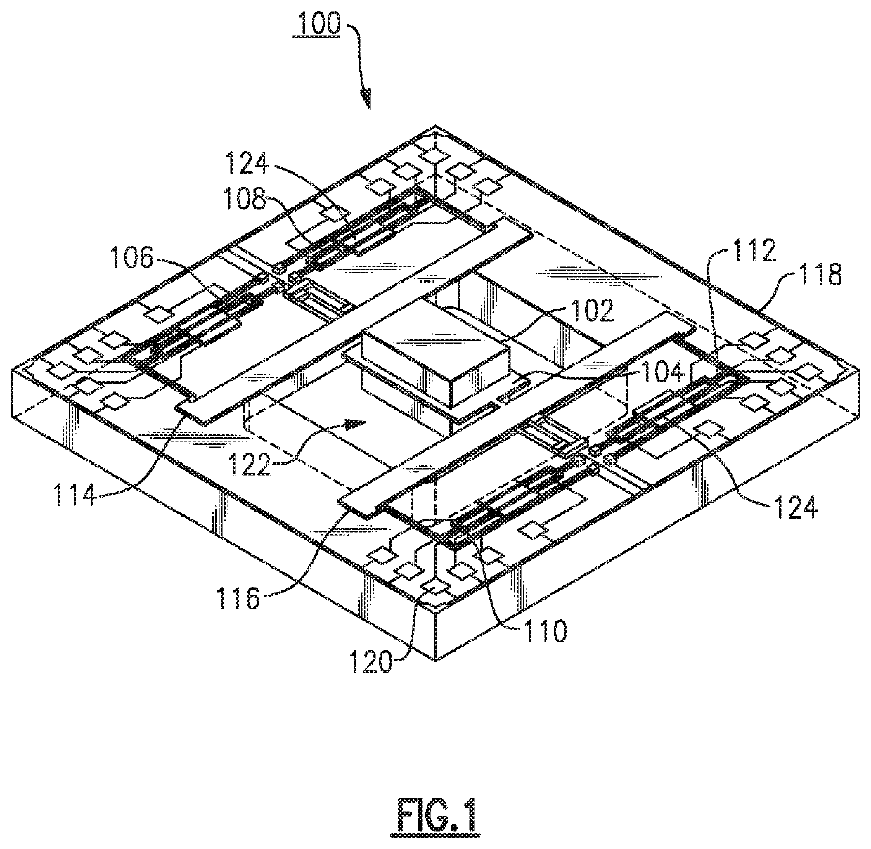
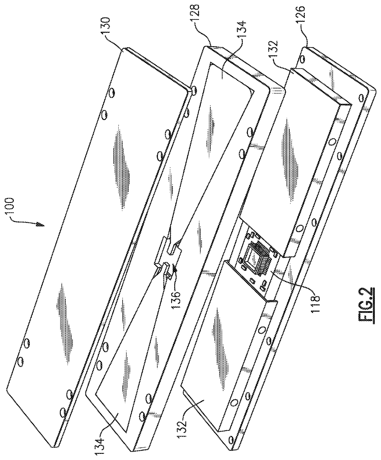
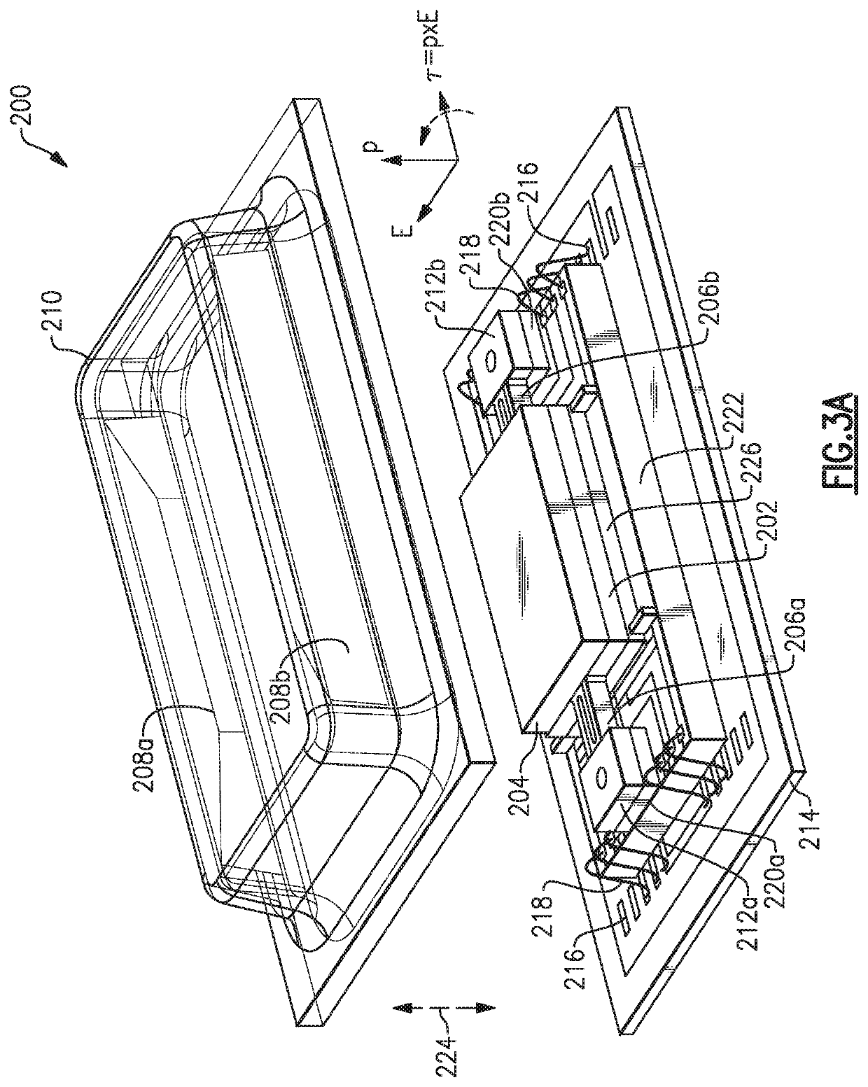
This patent describes a system for measuring magnetic and electric field gradients using micro-electro-mechanical systems (MEMS) sensors. These sensors can be integrated into a single device to measure the components of a magnetic and electric field gradient simultaneously. The system includes multiple torsionally operated MEMS magnetic sensors and electric field sensors that provide measurements of the magnetic and electric field gradients in response to a received magnetic or electric field. The system also includes control electronics to determine the magnetic or electric field gradient based on the measurements from the sensors. The integrated MEMS sensor system can be used in various applications such as magnetic and electric field gradiometry, as well as in the measurement of magnetic and electric field components in a magnetic or electric field generator.

Problems solved by technology

However, several important factors have made extending the magnetometer technology challenging.
One of the most recognizable issues is the presence of significant background interferers.
However, magnetic shielding is typically extremely expensive, and challenging to extend to free-field detection scenarios, such as searching for submarines.
Moreover, at very low frequencies, vibrations of the magnetometer sensors may produce interference signals as a result of the larger static magnetic field of the Earth.
Linear motion through the Earth's gradient is a factor, but for vector magnetometers, the greatest challenge is the rotational vibration (e.g., jitter), which may cause the very large background field of the Earth to be modulated into the sense bandwidth of the magnetometer.
This is especially problematic on moving platforms.
A scalar magnetometer may avoid the first order error by reducing the total number of degrees of freedom measured; however, scalar magnetometers are limited in the information that they can provide.
Likewise, the resulting jitter induced noise can be much worse and require high precision (<1 nrad / √Hz) instruments for compensation.
These instruments are often expensive and may not be available for some applications.

Method used


Image

  • Electromagnetic gradiometers
  • Electromagnetic gradiometers
  • Electromagnetic gradiometers

Examples


Embodiment Construction

[0029]Although magnetics technology may be viewed as mature, advancing applications continue to drive the need to develop and improve precision magnetometers. For example, the advent of low cost unmanned aerial vehicles, has provided an avenue to improve the cost effectiveness of large-scale magnetic surveys. This in turn drives a need to achieve very high levels of performance (low noise) while operating in the Earth field with low size, weight and power (SWaP).

[0030]The various challenges associated with magnetometers discussed above have prevented the widespread adoption of advanced magnetometer systems that operate in the open ambient field of the Earth. One approach to addressing the discussed challenges includes measuring a magnetic field gradient instead of the field itself. The gradient of clutter, which tends to come from distant sources, is remarkably different than the signal source, which tends to be at a much closer range to the sensor. Therefore, the gradient provides ...


PUM


Abstract

An electromagnetic gradiometer that includes multiple torsionally operated MEMS-based magnetic and / or electric field sensors with control electronics configured to provide magnetic and / or electric field gradient measurements. In one example a magnetic gradiometer includes a first torsionally operated MEMS magnetic sensor having a capacitive read-out configured to provide a first measurement of a received magnetic field, a second torsionally operated MEMS magnetic sensor coupled to the first torsionally operated MEMS magnetic sensor and having the capacitive read-out configured to provide a second measurement of the received magnetic field, and control electronics coupled to the first and second torsionally operated MEMS magnetic sensors and configured to determine a magnetic field gradient of the received magnetic field based the first and second measurements from the first and second torsionally operated MEMS electromagnetic sensors.

Description

CROSS-REFERENCE TO RELATED APPLICATIONS[0001]This application claims the benefit under 35 U.S.C. § 119(e) of co-pending U.S. Provisional Application No. 62 / 568,627 titled “MAGNETIC GRADIOMETERS AND METHODS” and filed on Oct. 5, 2017, which is herein incorporated by reference in its entirety for all purposes.BACKGROUND[0002]Precision magnetometers have existed for nearly a century. During the Second World War, flux-gate magnetometers were applied to detect submerged submarines based on the ferromagnetic properties of their hulls. Since the first use of magnetometers, technology has continued to advance to enable near-field, quasi-static, magnetometry in the extremely low frequency (ELF) band. Applications of this technology include proximity detection (e.g., ships, submarines, mines, etc.), energy resource prospecting, non-destructive testing of structures (e.g., civil infrastructure, welding joints, etc.), various biomedical applications (e.g., magneto-encephalography), communicatio...

Claims


Application Information

Patent Timeline
IPC IPC(8): G01R33/022G01R33/038G01R33/028G01R33/00
CPCG01R33/0082G01R33/0041G01R33/0286G01R33/022G01R33/038G01R33/0076G01R15/00G01R33/0094G01R15/14
Inventor BICKFORD, JAMES A.
Owner CHARLES STARK DRAPER LABORATORY
Learn More